Outcomes
Research Themes
The focus of this project was on the two major areas of the electrical drive train: the electric motor and the power electronics, as these are the basis of all LCVs. To aid in the study of these two main areas, the VESI project was broken down into six research themes, which drew on expertise in materials, heat flow, control, circuits, physics, electrical engineering, and mechanical design. What follows is a summary of the outcomes from these six research themes.
• The Power Semiconductor theme utilised a unique Silicon Carbide (SiC) epitaxial reactor to grow layers of 3C polytypes of SiC on a Si wafer. At the 1200-1700V range of devices used in the automotive drive-train, 3C offers an excellent compromise of blocking voltage and on-state performance with low cost. Low resistivity (in the order of 10-6 Ω.cm2) as well as thermally stable ohmic contact (up to 500 K) on nitrogen-implanted 3C-SiC layers were successfully obtained, which is sufficient for power device fabrication. More importantly, a carrier field-effect peak mobility approaching 70 cm2/V.s was demonstrated for the channel region of 3C-SiC lateral MOSFETs with O2 dry oxidised gate oxide. By introducing a high temperature nitridation process (≥ 1300°C), the peak mobility further increased to above 90 cm2/V.s, which is more than twice the value of a commercially available 4H-SiC MOSFET. The lateral diffusion MOSFETs (channel length 3 µm) fabricated on 3C-SiC turned out to have a specific on-resistance more than 10 times lower than their 4H-SiC counterparts with similar processing steps. These achievements confirm the potential of 3C-SiC in medium voltage MOS applications.
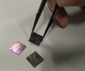
Figure 1: A bare die (12 mm x 12 mm) containing multiple devices
• The Design Tools theme was the largest theme within the VESI project. One of the areas of research addressed was the missing links in multi-physics simulation software. A questionnaire was sent out to determine customers’ requirements and expectations of the software, and the results obtained were submitted to software developers to help them enhance their software according to their users’ needs. The researchers also established a new mathematical description for convective heat transfer in electric motors, and developed an algorithm describing the heat transfer process of potted devices, and which enables a much faster computation time for multi-physics software. Besides addressing missing electric/thermal/mechanical links, this theme also focussed on the advancements of cooling. A new power module adaptor that sits between the power module and the cooling plate was built and tested, and was shown to provide a lifetime enhancement of a factor of two due to local active control of the thermal impedance. Research activity on cooling was also conducted on potted inductors, where the impact of new potting material was investigated - this culminated in a significant size reduction in potted systems.
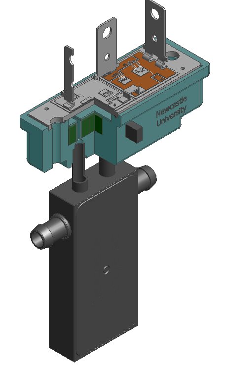
Figure 2: Intelligently cooled power module
• In the Packaging theme, accepted thinking on converter construction was challenged through: (i) an emphasis on integrated, modular assemblies which combine electromagnetic, thermal and mechanical functions rather than piecemeal assemblies of components, and (ii) a detailed consideration of operational constraints (e.g. available cooling medium) as well as electrical function. Activities focussed on the integration of high current density passive components which take advantage of an integrated thermal management system in order to increase energy densities, while developing low inductance planar device interconnect technologies. Current densities in excess of 100A per mm2 were achieved, opening up a wide range of application opportunities. These advances have enabled the realisation of a high-speed switching cell structure which can be used to generate larger power converters when used in a modular fashion, whilst at the same time minimizing the Electro-Magnetic Interference generated by the switching circuit. This has led to demonstrator power converters for automotive applications, which are inclusive of both the passive power components necessary for the operation of the converter together with the required EMI filtering components/structures resulting in increases in power densities of up to 200kW/litre.
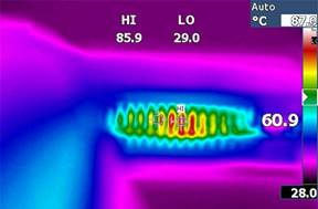
Figure 3: Thermal image of integrated inductor under test at 100A/mm2
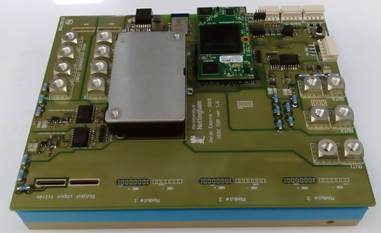
Figure 4: Final power converter realisation: DC-DC power converter, 300V In, 0-250V out, 52kW max rated power
• The Motors theme conducted research into three types of electric machine technology for electric propulsion applications, covering a wide operational speed range as well as addressing strategic supply chain issues that are highly relevant to the uptake of the EV market:
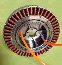
o An in-wheel direct-drive permanent magnet synchronous machine (PMSM) based on rare-earth PM material.
o A medium-speed high-performance PMSM based on ferrite PM material.
o A high-speed switched reluctance machine (SRM).
Multi-objective and multi-parametric optimization techniques based on genetic particle swarm and design of experiments were used to enhance the in-wheel direct-drive rare-earth PMSM performance over normal vehicle drive cycles, and to reduce the rare-earth magnet content by a concurrent design routine on the stator slots and rotor magnets. Nearly 20% in reduced costs and a 90% improvement in torque density were achieved compared to existing commercial products. The two main disadvantages of low remanence flux and ease of demagnetisation associated with motors made by ferrite PM were addressed by electromagnetic design, matched with control strategies. Research findings confirmed that a two-layer ferrite configuration generally delivers superior torque density, good overload capability, and improved capability to withstand demagnetization without compromising the integrity and manufacturability of the rotor. Furthermore, a unified design methodology for the controller was developed to track maximum power points and maintain margins of safety against demagnetisation. Mechanical integrity design and analysis were the main objectives for the high-speed SRM to ensure rotor safety and to improve the overall power density of the machine.
 ... ...
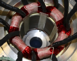
Figure 5: Stator of the in-wheel rare-earth permanent magnet motor; Figure 6: High-speed SRM stator
• The Converters theme investigated the main drive inverter, dc-dc converters and novel on-board charging configurations based on the use of multiphase machines and power electronics. A plethora of topologies were assessed against the criteria of adaptability, cost and reliability. A suite of new solutions were developed for full on-board integration of the battery charging. Different phase numbers for the stator winding of the propulsion motor and the drive inverter were investigated. It was shown that for each phase number equal to or larger than five, it was possible to achieve complete reutilisation of the motor stator winding as a filter and the drive inverter as a rectifier in the charging process, either without using any additional components, or by using a few additional switches for hardware reconfiguration between propulsion and charging modes. All the solutions provided both fast (three-phase) and slow (single-phase) charging without any development of electromagnetic torque during the process. Both charging operations and vehicle-to-grid mode power transfer were enabled. All solutions were shown to be applicable in conjunction with both induction and synchronous (all types) machines; hence savings in weight, cost and space were achieved. Three-port DC-DC converter topologies were also investigated to reduce the weight of the power electronics interconnecting the battery, traction drive and super-capacitor power buffer or fuel cell range extender. Non-linear control methods for DC-DC converters were examined to allow operation beyond traditional stability limits.
• Finally, the Passive Components theme took a fresh look at the design of magnetic components with the aim to improve the miniaturisation of these components, whilst studying how they may be better integrated into the final system. The groups involved focussed on the mass and volume reduction of wound passive components through the use of multi-physics design techniques. For example, 3-d Finite Element Models (FEMs) were developed for the eddy-current losses in high-frequency, tape-wound, nano-crystalline inductor cores, enabling accurate prediction of the intense heating within the core around the air gap, thereby providing a sound basis for design optimisation. A high-fidelity electromagnetic and thermal design tool applicable to E-core power inductor design was developed in which 2-d and 3-d FEMs were used for the electromagnetic and thermal modelling, respectively, while an FEM-informed analytical loss model was used to scale the winding losses with temperature, frequency and current. These modelling methods and their coupling were selected to provide a favourable trade-off between the model solution time, accuracy and fidelity. The models cater for non-transposed winding configurations, including circular and rectangular strip or edge-wound variants, and are parametrically defined to enable parameter studies or design optimisation to be performed. The tool was demonstrated by the design and experimental test of a high-energy-density filter inductor for an automotive application, achieving an energy density of 1.2 J/kg, representative of a factor of three mass-saving compared to commercially available components.
The Technology Demonstrators
The new knowledge and outputs from the six research themes enabled the researchers to design and build three technology demonstrators, beginning in October 2013, with the aim to generate industrial interest and investment beyond the VESI project’s duration.
Demonstrator 1: Integrated Non-Rare-Earth High Performance Drive
The Motors and the Design Tools themes joined forces to focus on cost reduction and power density improvement of the EV drive train through development of an integrated ferrite-based PM high performance drive as a viable alternative to the rare-earth PM traction motors. A multi-physics fundamental design approach was initially undertaken to allow for interacting requirements of electromagnetic, mechanical and thermal issues to be addressed and design specification optimised. To tackle the dual challenges of low remanence flux and high risk of demagnetisation of the ferrite magnets, a holistic design approach that linked electromagnetic optimization and drive control strategies was deployed in order to track maximum power output and maintain safe margins against demagnetization during operation.
This UK-led TRL-3 integrated ferrite-based PM motor drive technology demonstrator embodies an integrated heat sink for the motor and the power electronics with the following key features:
• 3-phase interior PM rotor configuration with a V-spoke layer of Y40 ferrite PM
• Rated at 280V, 20kW@5,000rpm
• Integrated electromagnetic and mechanical design of the rotor
• Concurrent electromagnetic and controller design for torque optimization and demagnetization prevention
• Compact embodiment of motor and power electronics parts with effective water cooling channels embedded in the motor housing.
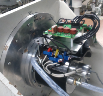
Figure 7: Integrated ferrite drive undergoing testing
Demonstrator 2: Integrated Power Conversion for Reduced EMI
This demonstrator combined a traction inverter and bi-directional DC-DC converter (each rated at 30 kW) within a single enclosure, taking an integrated approach to the electrical, thermal, mechanical, and EMI aspects of design, and resulting in a more robust and compact power conversion unit.
The demonstrator showcased a number of innovative technologies developed within the VESI project including energy dense AC line inductors, compact high-frequency magnetics and high-speed digital control for the interleaved DC-DC converter. A single, double-sided heat sink was developed for thermal management. A highly optimised design resulted from the application of advanced loss modelling and optimisation processes, and these techniques will form the basis for future design tools. Figure 14 shows a CAD image of the complete system, whilst Figure 15 shows the DC-DC converter during assembly.
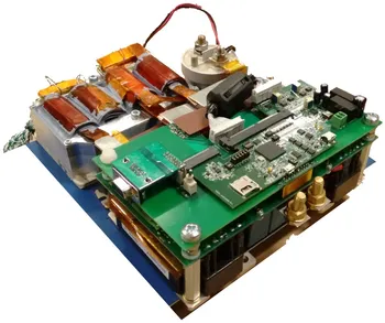
Figure 8: 30 kW DC-DC converter during assembly
Demonstrator 3: An Integrated On-board Battery Charger using a Highly Integrated Drive and a Nine-phase Machine, with Vehicle-to-Grid (V2G) Capability
The researchers designed and manufactured a fully working and portable demonstrator that enables bi-directional power flow. Its constituent parts are shown in Figure 16, and the assembled demonstrator in Figure 17 (10 x 12V LiFePO4 batteries are located on the lower shelf). The main functionalities include:
• Propulsion mode and battery charging/vehicle-to-grid (V2G) modes utilise exactly the same components.
• Not a single additional component is required, thus enabling savings on the space, cost and weight.
• Battery charging/V2G can be from both the single-phase and the three-phase grid (slow and fast charging).
• Completely torque-free operation during charging/V2G modes, hence no need to brake the machine.
• The charger is operational both with and without a DC-DC converter, depending on the battery voltage.
• Unity power factor operation occurs at the grid side during charging/V2G.
• No need for hardware reconfiguration for transitioning from propulsion to charging/V2G modes.
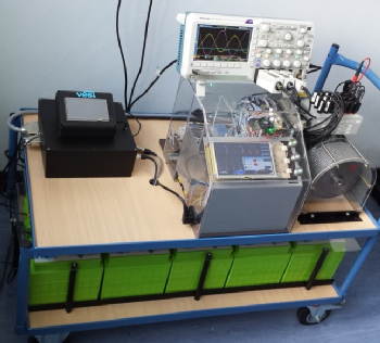
Figure 9: Completed demonstrator 3 assembly.