D-LACBED
In conventional convergent beam electron diffraction (CBED), the beam is focused to a small probe on the specimen. This gives a disc in the diffraction pattern for every diffracted beam.
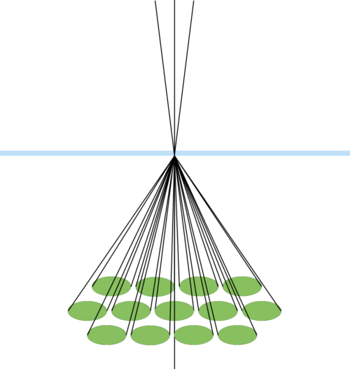
The field of view for any diffracted beam is limited; if the convergence angle is increased to give large-angle convergent-beam electron diffraction (LACBED), the discs in the diffraction pattern begin to overlap. The information in each beam can't be accessed separately if the beam is focused on the specimen.
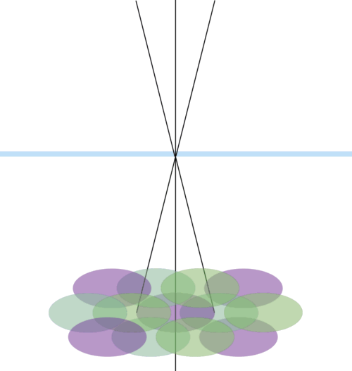
The usual way around this problem is to separate the cross-over point of the beam from the specimen plane, which allows an aperture to be used to block all beams apart from the one desired (which could be the straight-through 000 beam or one with a specific g-vector). This means that (1) the beam illuminates a much larger area of the specimen and (2) the aperture has to be moved to take every different LACBED pattern for all the g-vectors. (1) limits the type of specimen which can be examined; (2) has to be done by an operator - relying on their skill in operating the microscope, putting the aperture in the right place, and of course taking the time to collect an image of the diffraction pattern.
The DIGITAL solution
Using computer control, we can collect a series of CBED patterns and reconstruct the LACBED pattern by taking the appropriate part of each image. This allows the beam to be focused on the specimen and is relatively rapid; at an exposure time of 0.1s per image we can collect 1000 CBED patterns in less than 2 minutes.

Schematic showing computer-controlled beam tilting of the incident beam and the effect on a convergent beam diffraction pattern (green discs)
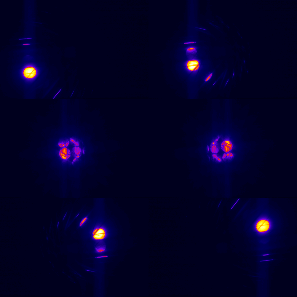
Experimental images captured using computer-controlled beam tilt and automatic image acquisition. Each disk is like a 'window' onto a different large-angle convergent beam pattern.
This has some similarities with the precession electron diffraction technique - a nice video showing beam paths in the TEM can be found here .
.
By taking the appropriate disc from each image and combining them into one, the D-LACBED pattern for each different reflection can be extracted. Three different D-LACBED patterns are shown below, all taken from the same dataset, together with patterns simulated using Pierre Stadelmann's jems. 125 different D-LACBED patterns could be extracted from the same dataset, giving a huge amount of detailed data.
0 0 0 beam
Left: D-LACBED pattern produced by taking the 000 beam from 169 individual Si [001] CBED patterns and recombining them to produce a composite image.
Right: A simulated 000 conventional LACBED pattern from a Si specimen 233 nm thick. Good correspondence is seen between experimental and simulated images.
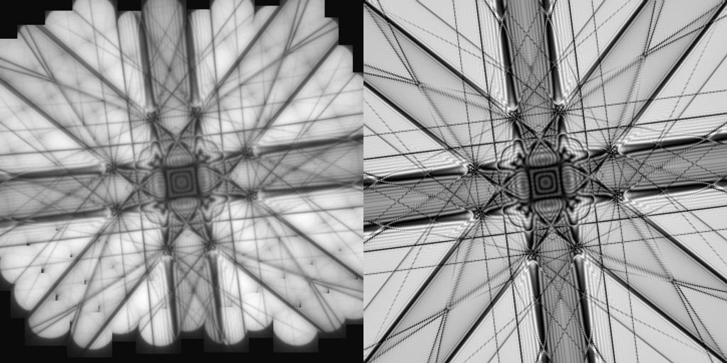
The electron beam size at the specimen was approx. 3 nm in diameter (FWHM). This is much smaller than is possible in conventional LACBED, where the sample is raised out of the plane of focus so that the selected area aperture can be used to block other (diffracted) beams.
2 2 0 beam
Left: D-LACBED pattern produced by recombining the 220 beam (disk below the 000 beam in the animation).
Right: Simulated 220 conventional LACBED pattern.
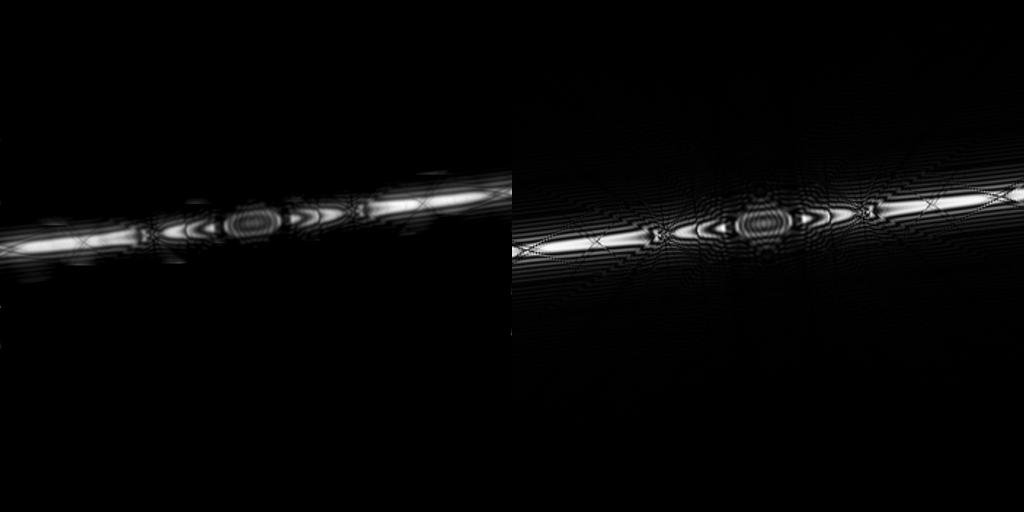
4 4 0 beam
Left: D-LACBED pattern produced by recombining the 440 beam (second disk below the 000 beam in the animation).
Right: Simulated 440 conventional LACBED pattern.
