12th October 2009: PE Measurement System Created on XMaS Beamline
The classic test for a ferroelectric is that it shows a spontaneous polarisation that is switchable by the application of an electric field, which is usually called a PE hysteresis loop. XmaS beamline scientists have been working with the NPL Functional Materials Group in order to set up an insitu system where measurement of the PE loop is carried out simultaneously with the X-ray characterisation. The NPL group specialises in developing characterisation methods for dielectric, piezoelectric, ferroelectric, and multiferroic materials and have helped to set up the system based on their good practice guide. Markys Cain and Mark Stewart from NPL, came to the ESRF beamline to commission the system and do some initial usability and verification tests.
Figure 1 shows PE loops taken on a soft lead zirconium titanate (PZT) composition, showing very clear ferroelectric switching, with a large remnant polarisation (polarisation at zero field), the characteristic that makes this type of material useful as a non volatile memory element. In fact this material had been previously poled at elevated temperature, which is the reason for the slightly non-symmetric polarisation behaviour, one direction is still more stable than the other. If the material were to be depoled by heating to above the Curie temperature, then the PE loop would show 2-fold rotational symmetry.
Figure 2 shows measurements on a ceramic multilayer capacitor which has piezoelectric (barium titanate based) ceramic layers sandwiched between magnetostrictive nickel electrodes. These commercially produced devices happen to show magnetoelectric coupling, but are normally used as capacitors at a maximum rating of 16 V. If however, as here, we apply a much higher voltage of 250 V, equivalent to a field of 250 kV/cm, we observe ferroelectric behaviour. This material has much lower remnant polarisation (it had not been previously poled) and so the curve is no longer offset about the zero polarisation axis and shows a purer symmetry.
Figure 3 shows a schematic of the system and these tests represent the verification of the electrical component of the system. As can be seen, the system is set up to be able to capture the signal from the X-ray detectors in a separate channel, and the next tests planned need to be carried out with live beam-time.
Work is continuing to improve the ease of use of the setup and iron out minor electrical noise issues, but it is now ready to use in anger. For more details on the PE measurement system contact Mark Stewart at NPL.
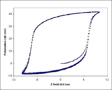
Polarisation Field (P-E) measurement of poled soft PZT composition taken at 1 Hz, five consecutive loops overlaid.
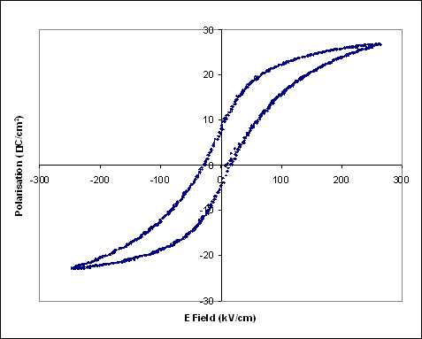
Polarisation Field (P-E) measurement of a 1 μF ceramic multilayer capacitor taken at 1Hz. The sample is a composite multiferroic with a sandwich of piezoelectric dielectric with magnetostrictive nickel electrodes.
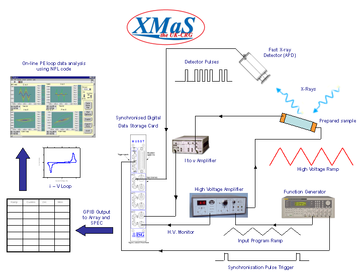
Schematic of in situ PE loop measurement system.