Beamline Details
Context
The ESRF-EBS (Extremely Brilliant Source) is a 150 M€ project to totally upgrade the ESRF storage ring, with a completion date in 2020. This upgrade has increased the brilliance on some of the insertion device beamlines by a factor of 100. The new lattice is replacing the old double bend achromat magnet sequence between the insertion devices with a new multi bend achromat design, increasing the number of bending magnets between the straight sections to seven.
The X-ray Source
This new low-emittance ring does necessarily mean major changes for all the bending magnet (BM) beamlines at the ESRF. The most significant impact is the removal of the old bending magnets as sources from the lattice. Within the new lattice, a space has been identified in which a small source with 2 mrad acceptance can be located. The new source position is slightly shifted with respect to the current source, about 2.7 m upstream. With the smaller acceptance, the source size is reduced but with quite improved brilliance, delivering a significantly smaller beam and increased power density within the beam. Various source options were considered: using a small insertion device, exploiting the steering magnets already part of the existing lattice design, or using a small 0.86 Tesla dipole positioned between two of the new steering magnets. Finally a choice was made to use the 0.86 Tesla “short bend” as the source for XMaS, as this provided a clean uncontaminated x-ray source and considerably more flux at higher energies, since the magnetic field of the dipole is more than double the 0.4 Tesla value of the old source (Fig. 1).
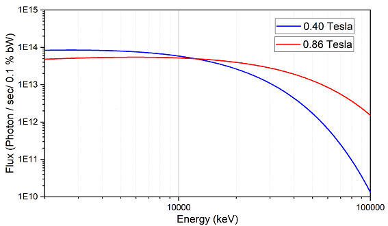
Figure 1. Calculated flux curves showing the flux from the previous 0.4 T, 3 mrad horizontal fan source (blue) and the flux from the 2 mrad fan of the new 0.86 T short bend magnet (red).
Optical Configuration
From the very first design studies of the upgraded XMaS beamline, it was decided to keep a very simple optical system consisting of a cryogenically cooled Si<111> monochromator and a toroidal mirror in a roughly 1:1 optical geometry. This simple, but robust system (Fig. 2) ensures that a diverse and interdisciplinary science program can be maintained. It is intuitive for users and allows for rapid changes of x-ray energy by simply rotating the monochromator Bragg axis and adjusting the distance between the first and second monochromator crystals. Downstream of the monochromator the next optical element is the toroidal mirror which focuses the beam onto the sample. In addition, for further beam conditioning, two flat harmonic rejection mirrors and a phase retarder can be employed. The largest impact of the EBS upgrade is the movement of the source some 2.7 m upstream within the lattice. Again, to ensure that the benefits from the new source are fully maximized, the experimental hutch has been extended by 4 m downstream and the diffractometer moved to maintain the current 1:1 focus. Overall, however, the upgrade will have a limited impact on the optical design but the main optical components will be refreshed to latest standards and re-designed to match the source characteristics.
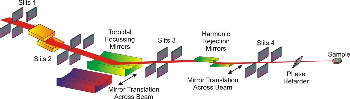
Figure 2. Schematic diagram of the optical configuration of the XMaS beamline. Post EBS upgrade, an additional toroidal focusing mirror will be used to extend the upper energy range of the beamline and to take advantage of the new smaller source, 2.7 m further upstream from the previous source.
Operating Modes
- Focused Monochromatic Beam (FMB): both the monochromator and the focusing mirror are used. The beamline is normally used in this configuration.
- Unfocused Monochromatic Beam (UMB): the monochromator is used, but the mirror is driven below the beam which passes unfocused into the experimental hutch. This allows a broad fan of monochromatic radiation to be used in the experimental hutch.
LN2 Monochromator
The old water cooled monochromator has been replaced by a new LN2 cooled system to cope with the increased thermal load from the new source, helping to reduce any heat-bumps. In addition, to exploit the flux at higher energies, the energy range has been extended from 2.035 keV to an upper range of approximately 40 keV. Directly cooled LN2 copper blocks are mounted to the sides of both the first and second silicon monochromator crystals, clamped using a predefined stress with a thin layer of indium metal between the copper blocks and the silicon crystal, to ensure good thermal conductivity. Both cooled crystals are thermally isolated by intermediate invar plates mounted onto ceramic balls, creating point contacts, thus minimizing thermal bridges between the crystals at cryogenic temperatures and the crystal cage at room temperature. Three high precision linear actuators control the distance between the first and second crystal, with the second crystal sitting on a three point kinematic mount. Also, the speed of the Bragg axis rotation has been increased to 1 degree per second.
Focusing Toroidal Mirrors
For focusing the beam, the same simple toroidal mirror geometry that was previously used has been retained. However, as the usable energy of the beamline is to be extended up to about 40 keV, new mirror coatings and angles of incidence were required. One particularly demanding requirement, primarily for XAS studies, was the ability to rapidly change energy between 2.035 and 40 keV whilst maintaining the focal spot at the same position. The old primary mirror was rhodium coated, with an incident angle of 4.5 mrad. Along with the mirror coating material, the angle of incidence effectively imposes an upper-energy cutoff for the beamline. To increase the energy cutoff, therefore we need a metallic coating with a higher density, and/or a decrease in the angle of incidence of the mirror. Platinum is a good mirror coating for higher x-ray energies, however the Pt L-edges present problems at lower energies, especially as Pt is an important catalysis material. It was therefore necessary to incorporate a second toroidal mirror, that could be translated into the beam, to maintain a clean energy spectrum across the entire 2.035 to 40 keV range. A chromium coating has been selected for the second mirror with the Pt mirror covering the energy around the Cr K-edge at 5.989 keV (Fig. 3). To ensure that the mirrors could be translated seamlessly and the focal spot to remain in the same position, the incidence angle for the two mirrors must be identical. The mirrors will use an angle of 2.5 mrad as this is the best compromise between the delivered flux for both high and low energies. One problem with operating x-ray mirrors at very low angles is that any ‘real’ mirror has a finite length and the incident beam from the monochromator will overspill the mirror at low angles resulting in a loss of transmitted flux, especially at lower x-ray beam energies where the vertical fan size increases. Considerable care has been taken when specifying the mechanics for these two mirrors to enable the focused beam to remain at the same point in space as the mirrors are translated across the beam. It is a non-trivial task to align two toroidal mirrors on a mechanical translation slide, as any small misalignment is magnified by the 25 meter lever from the mirror to the focal point of the beam. The motorized step resolution for the pitch motion will be <5 µrad and <5 mrad for the less sensitive roll motion. Both mirrors will have a new fixed sagittal radius and variable meridional radius, the latter being controlled by independent mirror benders. This proposed optical solution will deliver a clean energy spectrum from 2.035 to approximately 40 keV.
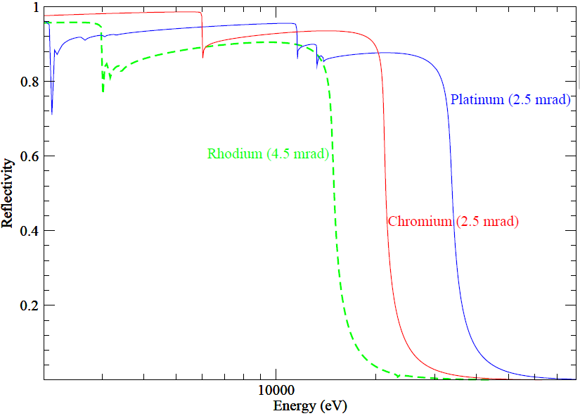
Figure 3. Chromium (solid red) and platinum (solid blue) reflectivity curves at 2.5 mrad (present configuration) versus rhodium (dashed green) reflectivity curve at 4.5 mrad (pre-EBS configuration).
Ray-tracing calculations
Ray-tracing calculations using SHADOW were performed to estimate the total flux transmitted assuming a 1.2 m long toroidal mirror, a 2 mrad horizontal fan of bending magnet radiation and an incident angle of 2.5 mrad. The mirror width was set to 120 mm, with the sagittal and meridional radii set to their theoretical values calculated by SHADOW. Incorporating realistic parameters for the optical elements has enabled us to model the new source characteristics as functions of both energy and focal length. We estimate the new focal spot size, about 60 µm horizontally x 70 µm vertically, to be significantly smaller than our current focused spot size of about 300 µm horizontally x 600 µm vertically but with a comparable flux (Fig. 4). As the source point has moved, aberrations in the beam shape are evident at the current diffractometer position but are minimised at the 1:1 focused position. Our experimental hutch has been extended by 4 m downstream which also allows additional beam defining and conditioning elements to be incorporated into the delivery design, increasing operational efficiency and allowing rapid switching between experimental configurations. As the majority of experiments performed on XMaS require a small footprint and/or a small angular divergence, the more brilliant source increases usable flux density for most users by one order of magnitude or more. Further increases in the S/N ratio are derived from the reduced background as the beam is no longer being defined close to the sample.
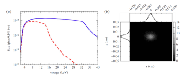
Figure 4. (a) A comparison of the flux at the sample through a 100 × 100 μm2 aperture for the pre-EBS (dashed red) and new (solid blue) source assuming realistic parameters for the mirror aberrations and absorption of beamline components. (b) Ray tracing calculation of the beam profile at the focused position.
EH1 layout
Figure 5 shows the 3D layout of the experimental hutch.
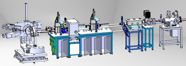
Figure 5. 3D layout of the new experimental hutch with the new beam delivery equipment such as in-vacuum ion chambers, phase retarder, absorption and calibration foils and quad-diode beam position monitor. An illustration of the upgraded diffractometer is also included.
Harmonic Rejection Mirrors
Currently the beamline has two additional mirrors further downstream from the focusing toroidal mirrors for the rejection of higher energy harmonics coming from the Si<111> monochromator. These mirrors are each 300 mm long and are fabricated from silicon substrates, with 1/3 of the mirror coated with a platinum stripe and 1/3 coated with a chromium stripe. For operation in the 6-15 keV region, the platinum stripe is used and the bare silicon section of the mirror below 6 keV. All of the existing mechanics that can perform a translation across the beam and adjust these mirrors up to 7 mrad angle of incidence are maintained.
Phase Retarder
The x-ray beam can be further conditioned by means of phase retarders (PR) to produce circularly polarized photons. The XMaS PR assembly was initially designed to perform polarization studies on rare-earth-based magnetic materials in the range of 7-9 keV where most of the L2,3 edges of the rare-earths are. The scientific interests at XMaS have diversified over the years with a strong need for low energies such as the S K-edge (2.47 keV) for catalysts containing sulphur for example. Nowadays, four different PR crystals are used to cover the energy spectrum between 2.4 and 13.5 keV, mostly for resonant magnetic reflectivity studies. As more space is available inside the extended experimental hutch since the EBS upgrade (Fig. 5), the new PR assembly, consisting of an Eulerian cradle with a high resolution circle for fine adjustment of the PR Bragg angle, is mounted inside an in-vacuum chamber to allow windowless operations. The four PR crystals are permanently mounted on a piezoelectric flipper device, the later being used to reverse the handedness of the x-ray beam helicity between left and right at a few Hertz. A linear stage allows the crystals to be driven in and out of the beam.
| Diamond thickness (µm) | Cut | Energy range (keV) |
| 800 | <110> |
5 - 13.5 |
| 300 | <110> | 3 - 5 |
| 100 | <001> | 3 - 5 |
| Silicon thickness (µm) | ||
| 5 | <111> | 2.1 - 3.0 |
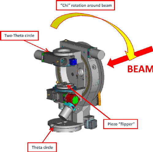
Figure 6. Schematic view of new phase plate assembly that is mounted into a vacuum vessel.
2D Detectors
With the ESRF-EBS new source, XMaS will increase the upper end of its operational energy range from 15 to about 40 keV. As the efficiency of silicon-based sensors degrades above 18 keV, it is necessary to invest in high energy sensitive detectors based on CdTe technology in order to realise the scientific potential of the new source. The higher energy range facilitates experiments on buried interfaces in more complex sample environments. Studies of solid-liquid interfaces relevant to electrochemical technologies become possible as the higher energy x-rays penetrate the liquid more easily. With the increasing use of in-operando studies, understanding the response of a sample to external stimuli under realistic operating conditions requires access to fast detectors. Repeatable processes can be studied by integrating data over a cyclic repetition but there is increasing need to study non-repetitive structural changes down to the tens of µs time resolutions. Other studies require high resolution setups. Exploiting the combination of spatial and temporal resolutions in real sample environments will facilitate the exploitation of the next generation of function systems.
With the choice of the x-ray source, a new suite of 2D detectors is needed. The choice is based on the resolution (pixel size), field of view (detector size), dynamic range and read-out speed with different applications requiring different detectors. All detectors must be compatible with ESRF control standards. Given the expected scientific portfolio, we need:
- A 2D for high energy (8 – 40 keV) photons using cadmium telluride (CdTe) as the sensor material; a sensor area of at least 80 x 40 mm2 with 75 x 75 µm2 pixel size and 24-bit counter with direct conversion; 2000 Hz with sub-millisecond readout times and a maximum count rate of at least 1x10⁷ photons/s/pixel. The X-Spectrum Lambda 750k CdTe detector was chosen.
- A large sensor area of at least 165 x 165 mm2 with a readout time of 2 ms. Operational energy to cover 5 to 36 keV and a frame rate of 25 Hz. Maximum count rate of at least 1x10⁷ photons/s/pixel. The Dectris Pilatus3 1M was chosen.
Counting Chain and Energy Sensitive Detector
As the beamline now performs a large range of x-ray spectroscopy experiments, both the single channel silicon drift diode (SDD) detector and the XIA Mercury pulse processor counting chain will be upgraded. It is proposed to upgrade the single channel detector to a multi-element SDD assembly. The Mercury system will be replaced by a new multichannel digital signal processing system (FALCON type).
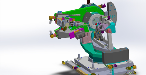
Upgraded Diffractometer
The heart of the instrumentation is the Huber 6-circle diffractometer. It has been totally refurbished by the manufacturer in Germany. The major upgrade being that the two-theta arm is being made substantially more robust, allowing heavier loads to be carried, whilst maintaining the same degree of precision. Also, there is two optical axes on the new two-theta arm assembly, allowing both analysers, point detectors and 2D cameras to be simultaneously mounted on the diffractometer.
 |
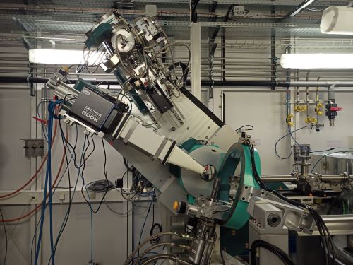 |
| Figure 7. New Huber diffractometer with the double 2θ axis (3D model) |
Figure 7. New refurbished Huber diffractometer with the double 2θ axis. |