Electrical Characterization of Samples at XMaS
P-E Loop System
The classic demonstration that a sample is ferroelectric is to measure a spontaneous polarisation (P) that is switchable by the application of an electric field (E) – namely a P-E hysteresis loop. The P-E loop system installed on the beamline uses either a direct measurement of the current across the sample or the Sawyer–Tower measurement method (Sawyer & Tower, 1930), shown in Fig. 1. The second method is privileged for two reasons. First, the environment surrounding the automated x-ray diffraction setup can be electromagnetically noisy because of the many stepper motor controllers that are needed to operate the system. This makes detection of small currents very difficult and it is more convenient to integrate the current on a sense capacitor, giving a degree of immunity to the electromagnetic noise. Secondly, whilst it may normally be possible to shield the sample from the noise by enclosing in a metallic Faraday cage, this is not consistent with the requirement to allow access to the sample for the incident and scattered/diffracted x-ray beams.
The sense capacitor for the Sawyer-Method [‘Sawyer–Tower method’] should be made from a low-loss dielectric material such as a polypropylene, polyester or polyphenylene sulfide. This is particularly important for the lower frequency measurements, where leakage currents across the capacitor could degrade the results. The size of the capacitor depends on two factors: the capacitance of the device under test (DUT) and the expected polarization of the DUT. An important consideration is that the voltage generated on the sense capacitor should be large enough to be easily measurable, usually greater than a few tens of millivolts, but not so large that it introduces a significant error on the voltage applied across the DUT. The polarization is calculated simply as the product of the capacitance of the sense capacitor and the electrometer voltage reading, divided by the area of the sample electrodes.
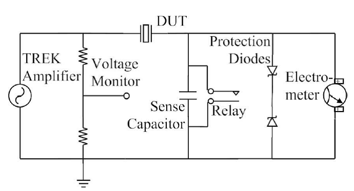
Figure 1: Circuit diagram of the Sawyer–Tower measurement system implemented on the XMaS beamline. The device under test (DUT) is placed in series with a sense capacitor. The voltage across the capacitor is monitored with an electrometer, and compared with the voltage applied to the DUT via the monitor voltage output from the amplifier. Back-to-back diodes are placed across the electrometer input for protection in the event of a sample breakdown. The circuit is shorted via a relay at the start of each experiment, or by shorting out the electrometer, via the beamline control system.
A typical P-E loop, after the electric field has been cycled at least once, should be closed, that is the polarization at the end of the cycle should equal the value at the beginning. An open loop can be the result of a real material effect, or due to instrumental factors, such as sense capacitor leakage, DC offsets on the applied voltage or electrometer drift. Resistive leakage from the sample will cause the voltage on the sense capacitor to continuously increase, and so it must be reset periodically by shorting the sense capacitor with the relay. This is also an important factor in keeping the sense capacitor voltage well below the Zener threshold of back-to-back diodes, which protects the electrometer in case of sample breakdown or other short-circuit conditions.
The measured P-E loop is dependent on the history of electrical loading on the sample. If the ferroelectric sample has been previously poled in the positive direction, the application of a negative field will cause domain switching, resulting in a large change in P and therefore a loop that is offset vertically from zero. To eliminate such effects, electrical conditioning of the DUT is required. The application of a cyclical electric field with amplitude decreasing over time should produce a gradual depoling of the materials, with a symmetrical polarization response on the next measured cycle.
Implementation on XMaS
The heart of the XMaS P-E loop system is the ESRF MUSST card (Multipurpose Unit for Synchronisation, Sequencing and Triggering) that records simultaneously the applied electric field and the electrical response from the electrometer, up to a sampling speed of 40 kHz. The output data file is a standard “SPEC”-type ASCII file and can be read using the standard beamline tools, such as “PyMCA”.
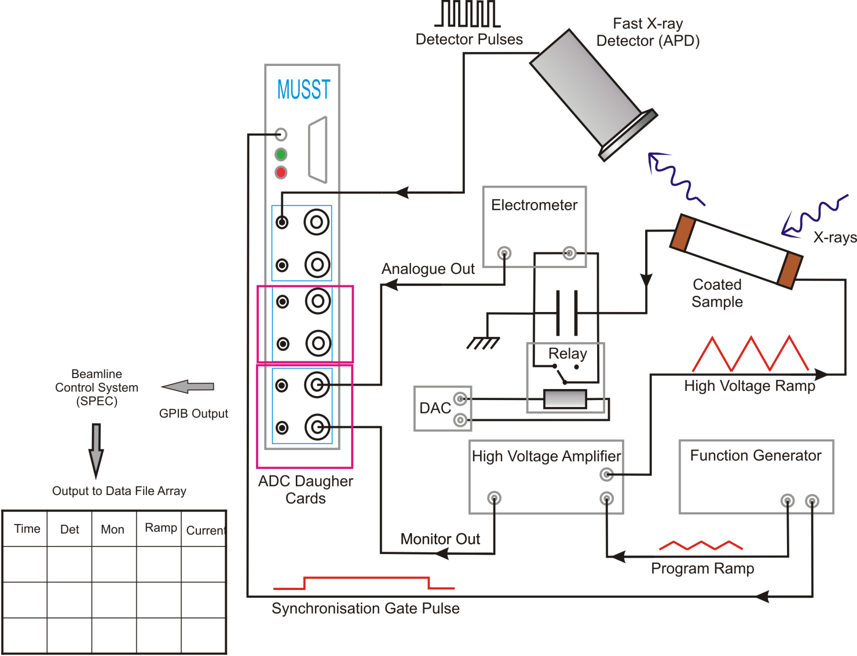
Figure 2. Schematic setup of the XMaS P-E loop system. The MUSST card is essentially an X-Y recorder and is synchronised with the signal generator. Note that the x-ray data acquisition does not necessarily need to be used if recording simple P-E loops without beam. The x-ray data will simply be a list of zeros in the data file.
Full details of the MUSST card can be found here.
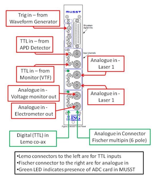
Connections for the MUSST Card.
TGA 1240 Waveform Generator
The TTi 1242 is a 2-channel waveform generator that drives and synchronises the XMaS P-E loop system. Each channel can operate as a full function generator with sine, cosine and square waves available between 1 mHz and 16 MHz. Triangle and ramp waveforms are available from 0.1 mHz to 100 MHz. This waveform generator can also be used to produce arbitrary waveforms or pulse trains. These waveforms are also available in a frequency range from 0.1 mHz to 100 MHz.
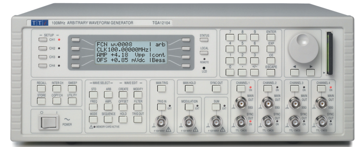
Figure 3. TTi Function Generator.
The P-E loop system is triggered by the TTi 1242 built in trigger system. When the pulse train is started, a short trigger edge will be produced on the “sync out”. When the pulse train is finished, a similar pulse will be produced. The MUSST card will record data on the analogue input channels at a sampling rate of 40 kHz between these two pulses on all of the analogue channels.
TREK High Voltage Amplifier (Model 610E)
High voltage electric fields are applied using the Trek 610E high voltage amplifier. Maximum output of this amplifier is ±10 kV with a maximum current of 2000 μA. The Trek amplifier is controlled via an analogue input voltage (±10 V). This can be generated be either the Digital to Analogue Converter (DAC) or the beamline function generator. Normally the DAC is used to control the Trek for D.C. field applications. There are two output ranges on the amplifier, 0-1 kV and 0-10 kV. The analogue ±10 V input corresponding to ±1 kV and ±10 kV respectively. During normal operations for applying electric fields, the controller is used in voltage supply mode, the current limit being set independently.
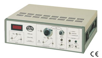
Figure 4: TREK Model 610E High Voltage Amplifier.
The full specification of the Trek Model 610E can be found at the following web link.
Keithley 6517B Electrometer
This Keithley electrometer measures the potential accumulated across the sense capacitor. The analogue output from this unit is fed directly into the MUSST data acquisition card. The electrometer must be set up to read “volts” when it is used as part of the Sawyer-Tower circuit. The signal input circuitry to this unit is very delicate and Zener diode protection should be used to insure that the unit is not damaged in case of sample breakdown.
This unit can also be used for the measurement of resistivity which will be described elsewhere and full specifications are here:
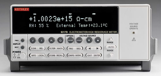
Figure 5: Keithley 6517B Electrometer.
Capacitor Bank
There is a range of 10 sense capacitors installed in the XMaS P-E loop system, ranging from 1 nF to 33 μF. By changing the value of the sense capacitor and “matching” it to the DUT, we can generate a voltage across this capacitor that can be easily read by the electrometer, thus providing a very large dynamic range to measure the polarization of the DUT. It should be noted that the input and output of the capacitor are BNC connectors and the signal output is a Trixial connector. Capacitors are changed by simply changing the input/output connectors and the signal out to the appropriate capacitor.
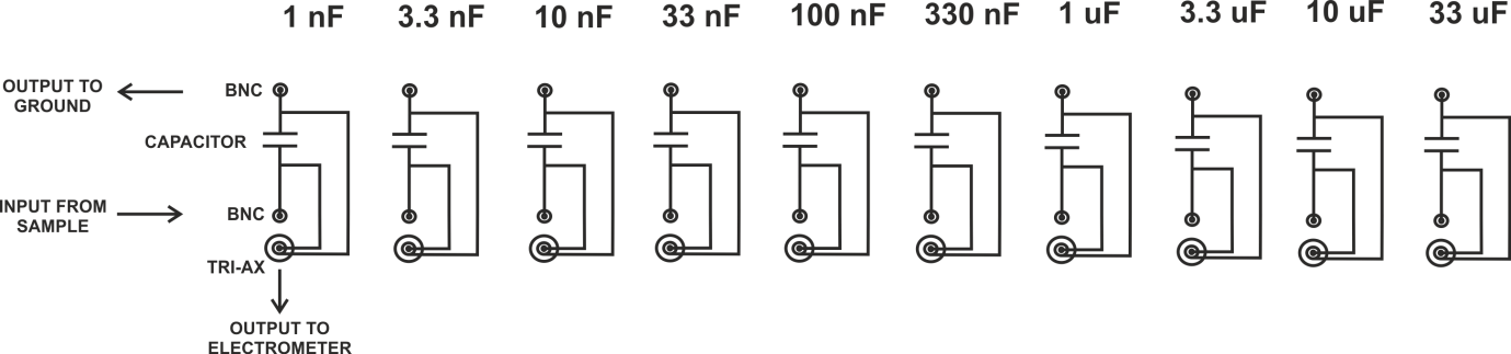
Figure 6: Schematic of capacitor bank.
General Considerations for Sample Environments
For experiments in air, it must be remembered that the maximum electric field that can be applied to a sample is normally governed by the breakdown of the air. This can be minimised by applying a thin layer of oil or grease to the sample. However, this can cause problems with the interaction with the x-ray beam – if present. Also, the sample should be thinned, so that the applied voltage to the sample is as low as reasonably possible, to minimise electrical breakdown on the wires applying the potential to the sample.
Software Implementation into SPEC
All of the equipment used to measure P-E loops on the XMaS beamline can be remotely controlled using the SPEC control system.
To create a new data file for the P-E loops, use the following:
435.LAB> newfastscanfile
Enter data file for bm28 electro chem fast scan (/data/bm28/inhouse/Paul/Warwick_PE/92_NBT_8BT_0_33_fast.02)?
Then type in the path and the name of the file that you wish to use.
To specify the amplitude, frequency, phase, sampling rate etc. of the PE loop measurement, we use a SPEC macro called “fastscansetup”. The last two questions refer to the use of the optical interferometer and can be answered with a “0” if this equipment is not being used.
436.LAB> fastscansetup
Number of cycles (10)?
Frequency of cycles (5)?
Amplitude of waveform (volts) (4)?
DC offset (volts) (0)?
Phase (degrees) (0)?
Number of data point to acumulate (2000)?
Do you want to reset Interferometer Analogue output (0)?
Do you want to turn On/Off the mirror (0)?
Global waiting time (s) (0)?
prepare_tga1240_burst
Setting 'bm28musst' as default MUSST unit.
To short out the sense capacitor on the system, simply type “shorty”.
References
Sawyer, C. & Tower, C. (1930). Phys. Rev. 35, 269.