Magnetic Fields
4 Tesla Superconducting Magnet (Design Concepts and Construction)
Currently there are two large and one in-vacuum magnets which can be mounted within the Huber diffractometer.
1 Tesla Electromagnet
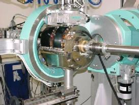
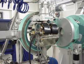
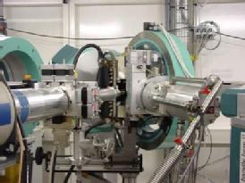
The 1 Tesla electromagnet at the XMaS beamline, supported from the base of the Huber diffractometer, fits within the Eulerian cradle as shown below. The geometry allows the magnet to be oriented in one of three positions 90° apart, about the vertical axis. Thus both transverse and longitudinal fields may be applied, allowing the separation of spin and orbital contributions to magnetic scattering signals. Also the magnet may be rotated to allow the application of a vertical field in a horizontal scattering geometry. The geometry of the yoke allows for the maximum number of field turns within the geometrical constraints of the diffractometer. It can deliver a field of 1.0 T in an air gap of 50 mm. To achieve this with a magnet of manageable size, water cooled hollow conductors have been used for the coils. A magnetically efficient yoke configuration occupies the lower half of the vertical scattering plane, leaving the other half open for the cryostat and scattered beam. The yoke and poles have been manufactured from ARMCO® grade iron. The gap set at 50 mm, the homogeneity of the field in the middle of the gap in a co-axial cylinder, a = 5 mm, r = 2.5 mm is within 2% of the central value. Conical pole tips can be mounted on the adjustable poles and, with a 25 mm gap, a field of 1.5 T is achievable at a current of 250 A.
 |
 |
 |
|
B horizontal and along the incident beam |
B horizontal and perpendicular to the incident beam |
B vertical and perpendicular to incident beam |
The magnet specifications with a 50 mm gap are summarised below:
-
Minimum axial field in magnet centre at 250 A: 1.0 T
-
Space with good field homogeneity: 5 mm x 2.5 mm ∅
-
Weight: 77 kg
-
Cryostat opening: 65 mm ∅
-
Horizontal beam openings: 5 mm ∅
-
Maximum field reversing time: 1 s
-
Inductance: 5.5 mH
-
Maximum current: 250 A
-
Voltage: 22.6 V
-
Power: 5.65 kW
-
Field homogeneity: 2%
4 Tesla Superconducting Magnet
The XMaS/AMI superconducting magnet has been designed to fit within the Eulerian cradle of the Huber diffractometer and allows three field orientations. The geometry allows the magnet to be turned along the vertical axis through 90º, facilitating application of magnetic fields both along and transverse to the incident beam direction. Thus, both transverse and longitudinal fields may be applied. This allows the separation of spin and orbital contributions to magnetic scattering signal in non-resonant ferromagnetic studies. It may also be mounted to provide a vertical field allowing additional contrast in resonant magnetic scattering studies. It can deliver a field of 4 T in a large 40 mm opening warm bore with a 180º scattering aperture. An efficient yoke configuration occupies the lower half of the vertical scattering plane, leaving the other half open for the cryostat and scattered beam. The geometry of the coil former has been optimized to allow for a maximum number of turns within the geometrical constraints of the diffractometer. The combination of the 4 Tesla magnet and low temperature insert at XMaS enables detailed studies of complex field and low temperature (~1.8 K) phase diagrams. The 180° scattering aperture allows access to large part of the reciprocal space, so that important information on magnetic wave-vector dependence can be readily obtained. As this magnet can be used in vertical or horizontal scattering geometry, experimentalists can take advantage of either incident σ-polarised or π-polarised photons from the ESRF storage ring.
DESIGN CONCEPTS AND CONSTRUCTION
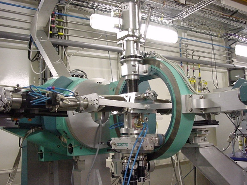
The primary design requirements for this magnet were that it should be able to operate in any angular geometry, thus necessitating a cryogen free design. It was also decided that the magnet should be able to fit within the Eulerian cradle of the Huber diffractometer. Another important criterion for the design was a 180° open warm bore access for the scattered x-ray beam, allowing access to a very large area of reciprocal space. The three versatile operation geometries of the magnet mounted within the Huber diffractometer are shown below:
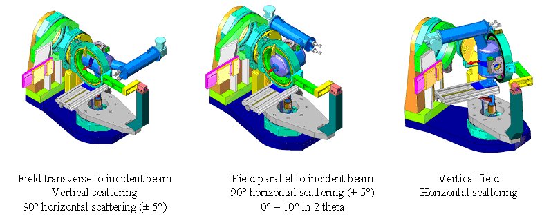 The XMaS/AMI superconducting magnet mounted within the Eulerian cradle on the Huber diffractometer, illustrating the three possible scattering geometries.
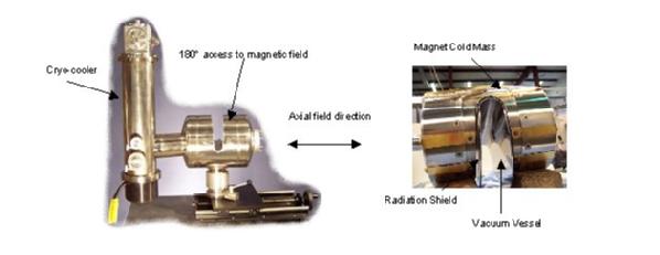
The superconducting magnet, shown below, is wound of twisted multifilamentary Niobium-Titanium (NbTi) superconductor embedded in a copper matrix. Twisted filaments maximise magnetic stability and minimise magnetic hysteresis. The former for the magnet coil is constructed of non-magnetic titanium alloy. Quench protection diodes are mounted within the magnet. The magnet system has been optimised to allow for a maximum number of ampere-turns within the geometrical constraints of the diffractometer. One of the most demanding requirements was the provision for 180° of clear room temperature radial access to the 4 Tesla central magnetic field, while maintaining a fixed, compact outer vacuum vessel which fits within the various Huber diffractometer configurations. At 4 Tesla, the split coil magnet produces a force of approximately 68 kN, which acts to collapse the 180° gap. The magnet former was designed to support these forces and be rigid enough to minimise coil movement, which could cause a premature quench (i.e., below 4 Tesla).
 |
 |
|
A view of the completed magnet is shown (left), depicting cryocooler and open room temperature access to the magnetic field. A partially assembled view is also shown (right) illustrating the minimal spacing between the magnet cold mass, thermal radiation shield and the vacuum vessel. |
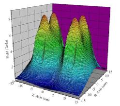
The 3D-magnetic field profile when the system is energised to 4.0 Tesla. Peak fields of ~8.5 Tesla can be seen within the windings at ~±7 cm along the z-axis. |
The field magnitudes are shown above, with the plots in the z-r plane. The z-axis is along the main axis of the split coil and the r-axis is along the radial axis of the split coil. Although the central field at z=0 and r=0 is 4 Tesla, the peak fields within the windings are approximately 8.5 T. This is approaching the critical field limit of about 9 Tesla for the Nb-Ti wire used in this magnet, with some margin for conduction cooling. A commercial Sumitomo closed-cycle refrigerator is used to cool the magnet system and AMI high temperature superconducting feedthroughs are installed to energise the magnet, whilst minimising the heat load on the refrigeration system. The requirement that the refrigerator should be located remotely from the magnet, due to the need for multiple orientations within the Huber diffractometer also caused a number of design concerns. The vacuum vessel of the magnet needed to support the weight of the refrigerator and to ensure a good thermal conduction path between the magnet and the cryocooler. Heat transfer between the magnet and the cryocooler is accomplished by thermal links located within the torque tube (LABEL). Differential thermal contraction is mitigated through flexible joints on both the first and second stage thermal links from the cryocooler. Another problem associated with multiple magnet orientations was locating the cold (< 4 K) magnet assembly within the radiation shield and vacuum vessel. Internal supports made from glass-fibre reinforced resin were designed to support the full weight of the magnet, about 34 kg, in radial and axial loading conditions, whilst simultaneously limiting the heat loads to the magnet to less than 200 mW. These supports also have to tolerate the dimensional changes due to the thermal contraction of dissimilar materials whilst locating the magnet in its correct position. In some areas, there is less than 4 mm between the cold magnet and the vacuum vessel at room temperature, as shown in the middle figure above.
The variable temperature insert is based around a RICOR 2/9 two-stage displex, capable of reaching 10 K. However, a third stage has been developed by the cryogenics group at the Institut Laue Langevin (ILL) in Grenoble. This novel device is capable of operating down to 1.8 K using 4He gas to within a few mK stability. It may also be operated over a wide range of angles without degradation of the base temperature.
In-Vacuum Magnet
The in-vacuum magnet has been designed to perform magnetic reflectivity (XRMR) measurements at low energies (down to ~3 keV) and low temperatures (~50 K). The whole magnet assembly is windowless to avoid absorption by entry and exit windows. The ±0.2 T magnetic field is applied in the plane of the sample and along the beam direction. The main body of the vacuum vessel has been constructed from aluminum. To ensure efficient cooling, the coil of the electromagnet is mounted ex-vacuum, below the vacuum vessel. The magnet yoke, which is made from ARMCO® grade iron, passes through the base of the vacuum vessel, sealed by double O-rings. An ARS DE202 displex sits on the xyz cryostat mount for precise sample alignment.
In-vacuum magnet mounted for low energy magnetic reflectivity (XRMR) measurements.