
Micro-Stereolithography and Additive Manufacturing Lab: Technology


(SEM Images of Coffee Cup Fabricated Using MSL)
DMD Technology
A Digital Micromirror Device, or DMD, is an optical semiconductor that is the core of DLP projection technology, and was invented by Dr. Larry Hornbeck and Dr. William E. "Ed" Nelson of Texas Instruments (TI) in 1987. A DMD chip has on its surface several hundred thousand microscopic mirrors arranged in a rectangular array which correspond to the pixels in the image to be displayed. The mirrors can be individually rotated ±10-12°, to an on or off state. In the on state, light from the projector bulb is reflected into the lens making the pixel appear bright on the screen. In the off state, the light is directed elsewhere (usually onto a heatsink), making the pixel appear dark.
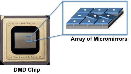
In MSL, a DMD chip can be used to project a dynamic mask image onto the surface of a photosensitive resin, polymerising the resin in a controlled shape.
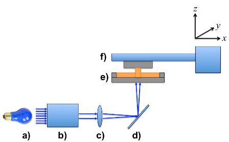
An MSL System
An MSL system is normally composed of several individual parts.
a) A light source of suitable wavelength to polymerise the photosensitive resin being used
b) A projection system, normally employing a DMD chip to project images.
c) Focussing optics to focus projected image and reduce size as necessary.
d) A mirror to project the images onto the underside of a tray holding the photosensitive resin.
e) A transparent tray holding the photosensitive resin.
f) A build-stage with controllable motion (normally in the z-direction)
MSL Part Design
To fabricate a part using MSL, the part must first be designed using Computer Aided Design (CAD) software. Once the part has been designed, the design is converted to a format where slices or layers are taken through it at regular intervals. These slices are then used as photo-masks during the MSL process.
The Building Process
First of all, the build-stage is moved down towards the resin tray with only a small gap (normally on the order of tens of microns) left between the stage and the resin tray. Then, the first photo-mask is projected on the layer of resin trapped between the build-stage and the resin tray. The layer of photo-polymerised resin then sticks to the build-stage. After the exposure, the build-stage is raised, then lowered back down leaving the same gap as used previously but between the top of the existing resin layer stuck to the build-stage and the resin tray. The build is then completed by carrying on this process for the full set of photo-masks generated from the CAD file.
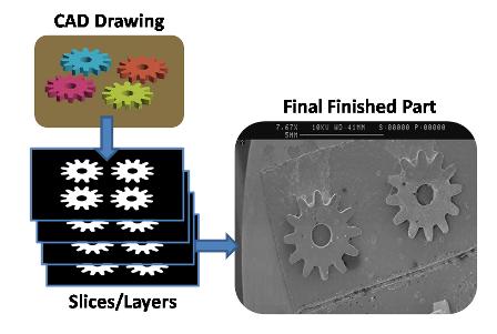

Above: SEM Image of cogs fabricated with MSL, Click for larger version