The EPR Cavity
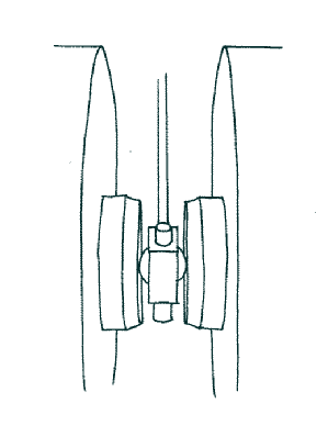 |
| Figure1. Illustration showing a spherical cavity between the poles of an electromagnet. A waveguide brings the microwaves down into the cavity. |
A resonant cavity acts to increase the energy density of microwaves at the sample thereby increasing the chance of observing resonant absorption. The energy density in the cavity can be thousands of times that in the waveguide. To fully understand the role of the cavity it is necessary to understand how the EPR signal is detected.
The cavity contains the sample and is positioned between the poles of an electromagnet such that the sample sits in a homogeneous B field. The external B field causes splitting in the energy of some electron spin states in the sample. The energy difference typically corresponds to microwave frequencies of electromagnetic radiation. A stable source of microwaves is generated in the bridge, usually from a klystron or Gunn oscillator, and travels down a waveguide into the cavity. When the energy of the microwaves corresponds to the energy difference in spin states, the microwaves can be absorbed and emitted; the resonant condition has been met. In principal the B field can be kept constant and the microwave frequency swept to detect the resonant frequencies, or equivalently, the microwave frequency can be kept constant and the B field swept. In practice the latter technique is used because it is technologically far easier.
Cavity Modes
Typical microwave frequencies used are ‘X band’ microwaves at 9.75GHz. These conveniently have a wavelength of about 3 cm, a suitable scale for components. If the cavity has dimensions that are integer multiples of the half wavelength of the microwaves, reflections from the walls of the cavity constructively interfere and a standing wave is formed thus giving rise to the high density of microwaves desired. The resonant modes are labelled transverse electric (TE) and transverse magnetic (TM). A subscript then denotes the number of half-waves that fit in the x, y, and z directions.
|
The transitions between electron spin states are driven by the oscillating B1 field of the microwaves. Thus the sample is placed at a position where B1 is at a maximum. Since E1 and B1 are in anti-phase, the maximum in B1 conveniently corresponds to a minimum in E1, minimising dielectric absorptions. The cavity is also usually designed such that the resonant mode used has B1 perpendicular to the external B field. The most common cavities used that meet these criteria are the rectangular-parallelepiped (TE102) cavity and the cylindrical (TE011) cavity.
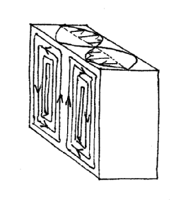
Different cavities are better suited to different uses. For instance the rectangular-parallelepiped cavity (Figure 2) has a low dielectric constant and is generous in the size and position of sample it allows. Because B1 is at its maximum at the center throughout the height of the cavity a sample can be placed at any height without large dielectric losses. This is especially useful for liquids permitting a sample tube to extend all the way through the cavity. The cylindrical cavity also allows samples to extend through its entire height and allows larger diameter samples.
 |
| Figure 2. Diagram showing the electric and magnetic fields in a rectangular-parallelepiped cavity. Notice that at the center the magnetic field is at a maximum and the electric field is at a minimum. |
Sometimes it is desirable to use a larger B field to increase the splitting of spin energies; however this requires the use of higher energy microwaves. A note should be made about the dependence of the maximum sample size on the wavelength of microwaves used. It is clear that the size of the cavity is dictated by the microwave wavelength, and the sample has to fit in the cavity. Fundamentally however the sample must be smaller still such that it sits in a minimum of E1. Table 1 shows the wavelength of various microwaves used to give an idea of the restriction that this places on the sample size.
Coupling
The cavity is critically coupled to the waveguide such that there is (ideally) no reflected power. There is an iris connecting the waveguide to the cavity. A screw with a dielectric tip in front of the iris effectively changes its size, adjusting the amount of microwaves that enter the cavity. The position of the iris screw is adjusted such that the impedances of the waveguide and cavity are matched. This is analogous to a wave travelling down a string which changes density at a given point. If there is a difference in density a proportion of a wave will be reflected at the interface between. When the densities match the wave is fully transmitted across the boundary.
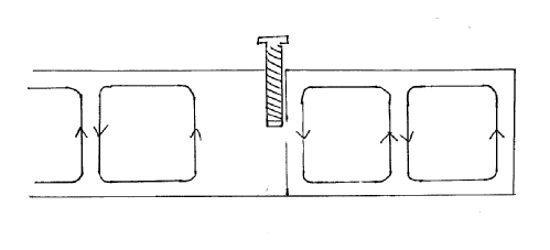 |
| Figure 3. Diagram of iris screw between cavity and waveguide. The position of the screw is adjusted to match the impedence between the cavity and the waveguide. |
If we measure the power reflected from the coupled cavity containing a sample it will ordinarily by zero (or rather, as close as we can get it to zero). As the microwave field is swept and a resonant condition is met exciting spin transitions, microwave power is absorbed in the cavity thus altering the impedance. The impedances of the waveguide and the cavity are no longer matched and power is reflected. It is this reflected power that is observed as an EPR signal. Since it is neccessary to critically couple the cavity to waveguide a restriction is placed on what samples can be placed within the cavity. As has been previously mentioned dielectric losses must be minimised since this changes the impedence of the cavity thus making it difficult or impossible to critically couple it. The more the sample extends into E1 the greater the effect.
Q Factors
The Q factor, or quality factor, is a measure of how under-damped a resonator is. In the case of a cavity this corresponds to how much microwave energy it stores. It is defined simply as
where the ‘cycle’ refers to one period of the microwaves. For high Q values it can be expressed in the more measurable form of
where νr is the resonant frequency and Δν is the FWHM. A high Q means the spectrometer will be more sensitive as the microwave density will be higher. The Q is lowered by interactions of the microwaves with dielectric materials in the cavity and by generating currents in the walls of the cavity resulting in heating. To minimise losses to the cavity walls they have a thick silver plating, which in turn is covered by a thin gold plating to prevent deterioration of the silver.
Further reading
Excellent accounts of EPR instrumentation including the cavity are given in the following books:
J. A. Weil and J. R. Bolton, Electron Paramagnetic Resonance: Elementary Theory an d Practical Applications, Second ed. (John Wiley & Sons, Inc., 2007).
C. Poole, Electron spin resonance: a comprehensive treatise on experimental techniques, Second ed. (Dover Publications, 1996).