Resonator Introduction
The resonator is an integral component in most electron paramagnetic resonance (EPR) spectrometers. It is not strictly necessary to achieve resonance, however in practice it is only the strongest of paramagnetic signals and very high frequency systems (where resonator geometries become difficult to engineer) that obtain an appreciable signal without one. An image of a standard Bruker X-band cavity resonator is shown below. Cavity resonators such as this can be thought of simply as a waveguide which has been short-circuited at both ends.
These resonator cavities are analogous to the air cavities in acoustic guitars or to blowing into an empty bottle, both examples giving an amplification of sound waves. This type of air resonance cavity is known as a “Helmholtz resonator” after the device developed by Helmholtz in the 1850s. The purpose of our resonators is to instead amplify the electric and magnetic field components of the microwave radiation, resulting in intense microwave radiation applied to a given sample volume.![Figure 1 ER4102ST X-band cavity resonator [1]](resonators_html_30ca9e50.jpg?maxWidth=156&maxHeight=222)
The amplification of both the sound and electromagnetic waves in these cavities is the result of the formation of standing waves terminating in the walls of the cavity. If an EM wave of a specific frequency enters a cavity, it will reflect back and forth within the space, forming a standing wave pattern with very low losses. As more and more travelling waves enter the cavity, they combine with the standing wave, increasing the energy stored within the cavity.
This cavity system is effectively the microwave analogue of the LCR resonant circuit, where we can observe a resonant frequency at ω0=2πf0=(LC)-1/2. This resonant frequency is generally made equal to the microwave frequency desired in an EPR experiment (generally we keep the microwave frequency stable whilst the magnetic field is swept), given by hν=guBB. As a result of this, the design of a resonator cavity must be such that the dimensions of the cavity walls are appropriate for the applied frequency. For X-band microwaves the frequencies correspond to a wavelength on the order of centimetres, which is convenient for the construction of devices. Moving up towards higher frequencies (and therefore larger applied magnetic fields and improved spectral resolution), the required dimensions become smaller and smaller. For example, a W-band spectrometer requires cavity dimensions on the order of millimetres.
In order to quantify the energy storage efficiency of a resonator, we can again look to the LCR circuit, which provides a parameter called the Q factor, defined as:
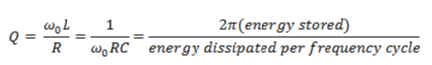
It is the last definition which is of immediate use. It tells us that the higher the Q factor of a resonator, the higher the energy intensity that is available for EPR transitions. It is also important to note that the Q factor of a resonator is related to the allowed bandwidth with high Q resonators being more selective (narrow bandwidth). Losses in resonator cavities generally arise from electric currents generated in the cavity walls and the dielectric losses from samples and material placed inside the cavity. In electrically detected magnetic resonance (EDMR) we encounter the additional difficulty of having an active driving current through a conducting sample placed inside the cavity. The presence of these additional fields results in distortion of the cavity modes and a reduction in Q factor.
In a high-Q resonator, the electric and magnetic fields are generally 90° out of phase with one another. This equates to electric field minima at magnetic field maxima and vice versa. We want our EPR sample to be present at the magnetic field maximum, as it is the magnetic dipole transitions that result in an EPR signal. In addition to this, any unwanted electric fields at the sample position will result in dielectric losses, reducing the Q factor. In order to alleviate this problem, cavity resonators are designed such that the dimensions allow sample placement on an electric field minimum.
Dielectric Resonators
A separate type of resonator which is common use in contemporary EPR spectrometers is that of the dielectric resonator. This can be considered as analogous to a standard resonance cavity, except the metallic walls are replaced by material of very high dielectric constant (such as ceramic). This large change in permittivity results in equivalent boundary conditions such that the resonance frequency is now dependent on the dimensions of the resonator (as before) and the dielectric constant of the resonator material (equivalent to the effect of the conductivity of the metallic walls before). The construction of the resonator is such that the microwave magnetic field is concentrated over the volume of the sample, increasing the filling factor.
An important difference from the metallic-walled cavity is that the electric and magnetic fields are not zero outside the walls of the dielectric resonator. They do, however, rapidly decay with distance away from the resonator such that the majority of the energy is stored within the resonator and the open circuit boundary conditions can be approximated as before.
There are several important advantages to using dielectric cavities over their metallic-walled counterparts, these mainly being reductions in size, weight and price. However, as with most situations, these advantages don’t come without their corresponding disadvantages of being more sensitive to temperature and mechanical fluctuations.
References
[1] Image Source: http://www.bruker-biospin.com/epr_res_standard.html
[2] C. P. Poole Jr., Electron Spin Resonance: A Comprehensive Treatise on Experimental Techniques, John Wiley & Sons Inc, Chapter 5, (1983)
[3] J. A. Weil, J. R. Bolton, Electron Paramagnetic Resonance: Elementary Theory and Practical Applications, John Wiley & Sons Inc, Appendix E, (2007)
[4] W.M. Walsh, L.W. Rupp, Rev. Sci. Instrum. 57, 2278 (1986)
[5] F.J. Rosenbaum, Rev. Sci. Instrum. 35, 1550 (1964)