Pre-EBS Beamline
Synopsis
The beamline is situated on a bending magnet at the ESRF and comprises a unique combination of instrumentation for high resolution and magnetic single crystal diffraction. White beam operation is possible, as well as focussed and unfocussed monochromatic modes. An 11-axis Huber diffractometer facilitates sample operation in both vertical and horizontal scattering geometries. In addition to harmonic rejection mirrors, the beam can be further conditioned by various phase-plates and an in-vacuum polarisation analyser. Standard scintillator detectors, avalanche photodiodes, Si drift diodes, a MAR CCD and 2D pixel detectors (Pilatus3 300k, Maxipix 2x2) are regularly used. Sample environment ranges from 1 K to 800 K (1300 K on request). A 1 Tesla electromagnet and a 4 Tesla superconducting magnet can be used in either vertical or horizontal scattering geometries. An in-vacuum 0.2 Tesla electromagnet originally designed for low energy x-ray reflectometry studies is also available.
The X-ray Source
The ESRF storage ring circulates electrons at an energy of 6.04 GeV and a maximum current of 200 mA. It consists of: an 844 m circumference storage ring fed from a 300 m circumference 6 GeV booster synchrotron and a LINAC pre-injector. The ESRF synchrotron was initially conceived to provide only insertion device source points, undulators and multipole wigglers. During the design evolution it was realised that the dipole magnets could provide excellent additional sources, albeit with less intensity, but without compromising their more powerful neighbours. The dipoles have been designed to give a fringing field having a flat intermediate step at 0.4 T, half of the full field, 0.8 T. This produces a critical energy in the photon beam of 9.8 keV, half that for sources on the 0.8 T section. The XMaS beamline uses a 0.4 T section as its source point.
The Beamline
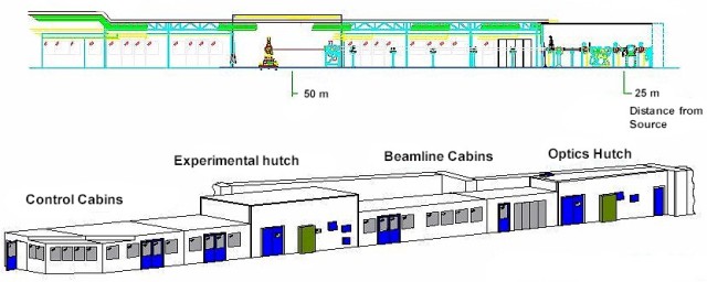
The XMaS beam line has been designed to perform experiments over an energy range of 2.4 to 15 keV. The beamline is sited on the soft end of dipole 28 (critical energy 9.8 keV) and the beamline layout is shown below.
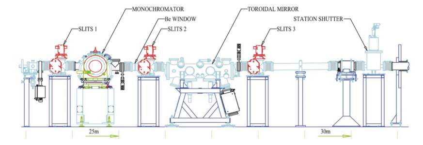
The optics, shown schematically below, consists of a double-crystal monochromator followed by a toroidal mirror. The monochromator comprises two plane silicon crystals, currently silicon (111), mounted in a crystal cage which maintains a constant 20 mm offset for the exit beam. The first crystal is water cooled and absorbs most of the incident synchrotron radiation power. The mirror, uncooled, is made from single crystal silicon and has a sectored cylindrical cross-section of 116 mm radius (sagittal). The small cylindrical curvature required tangentially, 5.5 km, is produced by a pneumatically actuated bending mechanism. The two curvatures thus form the toroidal surface that focuses the beam to a small spot onto the sample surface. To enhance the mirror reflectivity up to 15 keV the surface has been coated with a thin layer of rhodium. The maximum flux collected comes from a fan of radiation of 3.1 milliradians horizontal width and 0.2 milliradians vertical height. The grazing angle of reflection is 4.5 milliradians. For more facts and figures see the summary of Beamline Technical Specifications.
Operating Modes
- Focussed Monochromatic Beam: both the monochromator and the focussing mirror are used. The beamline is normally used in this configuration.
- Unfocussed Monochromatic Beam: the monochromator is used, but the mirror is driven below the beam which passes unfocussed into the experimental hutch.
- White Beam: the monochromator crystals are moved away and the X-ray beam passes above the mirror. A narrow fan (10 mm horizontal at 47 m from the source) of white beam radiation is then delivered into the experimental hutch.
Energy Range
|
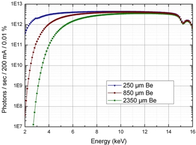
2.4 keV - 15 keV continuously tunable (focussed monochromatic mode). The flux deliverable to the sample depends on the exact sample environment used. In the figure we show calculated energy spectra for the beamline for three common operational modes. The standard flux at the end of the beam tube, as per the original technical design, is shown in red with 850 μm Be in the beam path. Experiments using a regular displex cryostat with two Be domes (2360 μm) result in the green curve. To facilitate low energy operations, the front end Be has been reduced from the original design. High vacuum sample environments and a removable Be window enable the beamline to operate in HV conditions. In this case the only absorper in the flight path is the thinned front end Be window (250 μm). The blue curve is the typical flux delivered when the beamline is configured for low energy operations. |
 |