Beamline Delivery System
Harmonic Rejection Mirrors
Phase Plates
Flipper
Modular Sections
Tube Slits
Harmonic Rejection Mirrors
A double-mirror harmonic rejection system is installed in the experimental hutch to overcome harmonic contamination from the monochromator. This contamination is also amplified by preferential absorption of the Si (111) reflection in the beryllium windows compared to the (333) and (444) reflections. The Pyrex® mirrors are currently being replaced by silicon mirrors. An picture of the old mirror system is shown below.
 |
Phase-Plates
The synchrotron incident linear polarised radiation can be converted into circular polarisation Pc by using a quarter-phase-plate. Circular polarisation can also be obtained from x-rays emitted above or below the electron orbit. The former technique is the only way to look at highly anisotropic magnetic materials for which the direction of the sample magnetisation cannot be reversed. The phase retarder assembly is situated about 3 m upstream of the diffractometer. The phase-plate crystals are mounted on a Huber goniometer and are driven to their quarter-wave-plate conditions, for maximum Pc, with a theta and a chi circle. The former rotation stage, which moves the crystal off the Bragg condition, has an accuracy of 0.0001° (0.36 arcseconds). It is orthogonally mounted on the chi circle. The chi rotation sets the optical axis of the phase-plate at 45° to the incident and plane polarisation, with an accuracy of ±10 arcseconds. A counter-balance is also mounted onto the arm of the chi circle. These two rotations are positioned upon two translation stages giving horizontal and vertical adjustment within 10 µm. All the motors are controlled from the SPEC software, which is also used elsewhere on the beamline. The theta circle has an encoder installed. A full description of the operation of phase-plates on XMaS can be found here.

Currently there are three diamond and one silicon phase-plates at XMaS, which are described below:
| Diamond thickness (µm) | Cut | Energy range (keV) |
| 800 | <110> |
5 - 13.5 |
| 300 | <110> | 3 - 5 |
| 100 | <001> | 3 - 5 |
| Silicon thickness (µm) | ||
| 5 | <111> | 2.1 - 3.0 |
Flipper
Specific spectroscopy experiments such as X-ray Magnetic Circular Dichroism (XMCD) require to reverse the degree of circular polarisation (or helicity) at a few tens of Hertz in order to improve the signal-to-noise ratio. In that respect, a piezo driven oscillation stage, the so-called flipper, was designed by the National Physical Laboratory, NPL (UK). The device uses two pairs of multilayer piezoelectric stacks mounted on opposite sides of, and coupled to, an aluminium plate which is free to rotate via two weak links. They are driven in opposite directions to provide displacement of up to 350 arcseconds. This specification, considerably larger than for usual devices, allows each diamond or silicon to be used in a wider energy range. A second advantage is that this flipper is very compact compared to existing oscillation stages and allows easy mounting on the phase-plate Huber 410 circle. The phase-plates are attached to an aluminium frame, mounted onto the aluminium plate with weak links. Two manual linear translations allow positioning of the phase-plate crystals at the centre of rotation of the phase-plate assembly.
In normal operation, the flipper is driven by a 11.5 Hz trapezoidal wave form generated by a TGA1240 arbitrary wave form generator. The signal is amplified by a PI LVPZT amplifier unit and then sent across both piezo pairs.
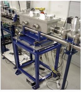
Modular Sections
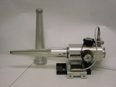
A flexible modular beam delivery system is installed in the experimental hutch allowing the continuation of an air-free path from the beamline final slit vessel to the diffractometer. It is comprised of two tubular assemblies vertically displaced, the lower tube encloses the unfocused monochromatic or white beams and the upper one the focused monochromatic beam. The main stand can accommodate modular vessels, some above and some below, mounted on X95-compatible carriages. Modules are provided that contain beam intensity monitor, motorised anti-scatter slits, pneumatically operated attenuator foils, absorption/calibration foils and a quad-diode beam position monitor (XBPM). The system is terminated using adjustable length telescopic tubes that allow continuation of the vacuum path close to the sample position. The vacuum tube is closed with a beryllium, kapton or mylar widowed flange.
Tube Slits
These slits were developed in order to define the incident or outgoing beam at a position very close to the sample. The adopted design satisfies three basic requirements, namely to define a footprint on a sample, to reduce background scatter and to enable isolation of small regions of interest on the sample. The assembly may equally well be mounted on the incident or diffracted beam path. In order to avoid possible collisions with the diffractometer, all of the actuation mechanics are spatially separated from the sample position, with the four independent slit jaws positioned by a system of levers as shown below. The maximum overall opening aperture of the slit assembly is 2.4 x 2.4 mm and each jaw can be independently positioned to micron precision. The slit assembly may be mounted on X95 compatible optical rail and is therefore interchangeable with other beamline modular components. Motion is provided to the levers through in-house designed miniature linear vacuum feed-through with limit switches fitted on all translations.
 |
 |
| 3D Model | Assembled tube slits in use on XMaS |
These slits are now Huber products and technical details can be found here.