Detectors
The following detectors are available for use on the beamline:
0D Detectors |
|
2D Detectors |
| Avalanche Photodiodes | MAR165 CCD Camera | |
| Bicron NaI Scintillator | PILATUS3 300K | |
| Cyberstar Scintillator | MAXIPIX | |
| Vortex Si Drift Diode |
Bicron NaI Scintillator
This X-ray detector consists of a cleaved NaI crystal with a 125 µm thick beryllium window mounted into a housing behind a removable brass collimator. A low noise photomultiplier tube, optically coupled within the housing connects a low noise voltage divider with a FET preamplifier. The output signal is fed into an ORTEC amplifier, onto a single channel analyser (SCA) and then into the VCT6 VME counter card, which in turn is read by SPEC.
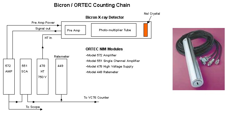
It is important to note that the bias voltage for the Bicron detectors is positive and negative for the solid state detector.
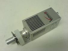
Cyberstar Scintillator
The Cyberstar detector uses a NaI(Tl) scintillator crystal providing a working energy range up to 50 keV. The detector aperture is 32 mm in diameter with a beryllium window of 200 µm thickness. After the scintillator there is a photo-multiplier tube with the photo-cathode adapted to the NaI(Tl) scintillation wavelength. The photo-multiplier has a typical gain of 106 providing an output pulse with rise time of 2.8 ns. Directly attached to the dynode chain is a fast preamplifier.
In the back part of the detector housing are a Lemo ERA size zero connector for the high voltage and an Anphenol 17DMW connector for the preamplifier power and signal output.
The control electronics is a Cyberstar Model CS93PPU. This electronics integrates the high voltage power supply, the shaping amplifier and the single channel analyser. In the rear panel is a DB9 female connector for the preamplifier power, a BNC for the signal input and a high voltage SHV connector for the photo-multiplier high voltage output. The unit is equipped with a serial line communication port configurable between RS232 and RS485. The DB9 male serial line connector is located in the rear panel.
The photo-multiplier voltage is adjustable between 250 V and 1250 V by means of a 10-turn potentiometer in the front panel. A 3 1/2 digit led display provides the reading of this voltage. The amplifier gain can be continuously adjusted between 0 and 10 by a 10-turn potentiometer located in the front panel. The shaping constant can be changed by a 4-position rotary switch. The low level discriminator threshold and the upper level threshold are adjustable between 50 mV and 10 V by two 10-turn potentiometer in the front panel. A 4-positions rotary switch is used to change the operation mode of the window discriminator:
| n (normal) | Upper and lower level are separately adjustable between 0 and 10 V. |
| i (integral) | Upper level disabled. |
| a (asymmetric) | Upper level adjust the window between 0 and 1 V above the lower level. |
| s (symmetric) | Upper level adjust symmetrically between 0.5 V and -0.5 V above and below the lower level. |
The amplified signal is present at the signal out BNC connector in the front panel. The discriminator output is a TTL or negative current fast NIM logic level jumped selected in the printed circuit board. The output signal is accessible at the window out BNC output in the front panel.
The control unit can be remotely controlled through the communication port. To use this feature the local-remote switch in the front panel must be set to remote (red light on). The SPEC macro to control the cyberstar is called "CYBERMENU"
For an energy of ~ 8.5 keV the following settings have been used:
- Gain: 30
- High Voltage: 1000 V
- Peak Time: 300 nano seconds
- Levels: 0.5 - 10 V
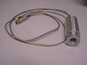
Vortex Si Drift Diode
|
Vortex® multi-cathode X-ray detectors feature the largest active area single element detector (~50 mm2, 8 mm diameter) available of its kind. Vortex® detectors are produced from high purity silicon using state-of-the-art CMOS production technology. They feature excellent energy resolution (<136 eV FWHM at Mn Kα is typical) and a high count rate capability (input rate >1 Mcps). At a very short peaking time of 0.25 µs, an output count rate of 600 kcps is achieved. A unique feature of these detectors is their ability to process high count rates with virtually zero loss in energy resolution and no peak shift with count rate. The detector at XMaS features a 25 µm thick Be window mounted onto a KF-40 vacuum flange, reducing air absorption. |
 |
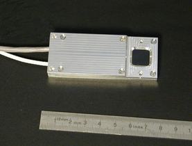
Avalanche Photodiodes
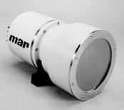
Avalanche Photodiode detectors (APD) are available and offer a very high dynamic range and linearity. They consist of PerkinElmer silicon avalanche photodiode chips with an integrated preamplifier. Two types of APD are available on the beamline: one with a chip of 10 mm x 10 mm active area shielded by a kapton window and another one with a 5 mm x 5 mm active area protected by a 80 µm thick Be window which is mounted onto a KF-16 vacuum flange.
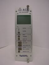
Each APD is controlled by an ACE unit through SPEC. This module includes a user interface in local and remote control mode. SPEC communicates to the module through a RS232 serial line port.
 |
 |
 |
|
APD with KF-16 vacuum flange (5 mm x 5 mm PerkinElmer chip) |
Standard APD (10 mm x 10 mm PerkinElmer chip) |
ACE unit |
MAR165 CCD Camera
|
The MAR165 CCD camera is a 2D detector with a round, 165 mm diameter active area. It has overall dimensions of (WxHxD): 220 x 220 x 340 and has a weight of ~20 kg. It uses one 4k x 4k chip, permanently bonded to a single fiber-optic taper. The camera reads the chip from four channels (quadrants) simultaneously, resulting in a 2048 x 2048 pixel image. The readout time is ~5 seconds. The pixel size is 80 µm x 80 µm. The MAR camera is controlled from SPEC, by specific macros, through a Linux device server running on xmas6 holding the camera controller card. The full MAR165 technical sheet is available here. |
|
PILATUS3 300K
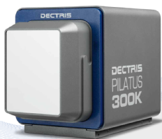
| The Dectris Pilatus3 300K is based on the newly developed CMOS hybrid-pixel technology and operates in single-photon counting mode with a point spread function of 1 pixel only (FWHM). The detector has dimensions of (WxHxD) of 160 x 194 x 262 mm and weighs approximately 7.5 kg. It reaches a framing rate up to 500 Hz with a 0.95 ms readout time in fast mode. The pixel size is 172 µm x 172 µm. The active area has 487 x 619=301453 pixels and 83.8 x 106.5 mm2 size. The detector has three modules with 17 pixels in the intermodule gap. The detector has a 20-bit dynamic range (counter overflow state 1048573) and a ~107 ph/s maximum counting rate per pixel. It can operate in the ~3-36 keV energy range. An external 5V TTL signal can be used to trigger the detector. |
|
PILATUS 300K-W
|
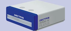
Only available on request !!! This detector has dimensions of (WxHxD) of 384 x 100 x 458 mm and weighs approximately 12 kg. It reaches a framing rate up to 200 Hz with a 2.7 ms readout time in fast mode (100 Hz and 3.6 ms in standard operation) and has a pixel size of 172 µm x 172 µm. The detector features 1475 x 195 pixels (3 x 1 chips). The Pilatus 300K-W consists of a detector head connected to a Linux acquisition workstation by a fiberoptic link. The detector head includes the detector module, the interface board with connection to the acquisition workstation, and power supplies. The acquisition workstation device server is based on the "LIMA" software library developed by the ESRF for 2D detectors control and 2D data acquisition. The Pilatus 300K-W technical sheet is available here. |
 |
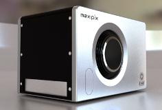
MAXIPIX
|
The MAXIPIX is a fast readout, photon-counting pixel detector system developed by the ESRF and based on the Medipix2 readout chip developed by CERN and the Medipix2 collaboration. It has dimensions of 145 x 140 x 222 mm and weighs about 4.7 kg. The system achieves up to 1.4 kHz frame rate with 0.29 ms readout dead time and has a pixel size of 55 µm x 55 µm. The available detector features 512 x 512 pixels (2 x 2 chips). ---A 1280 x 256 pixels (5 x 1 chips) detector is also available only on request!! --- MAXIPIX consists of a detector head connected to a Linux acquisition workstation by a fiberoptic link. The detector head includes the detector module, the interface board with connection to the acquisition workstation, and power supplies. The interface board can drive detector modules implementing up to five Medipix2 or Timepix chips with simultaneous readout of each chip. The acquisition workstation device server is based on the "LIMA" software library developed by the ESRF for 2D detectors control and 2D data acquisition. Maxipix technical sheet available here. |
 |