Diffractometer
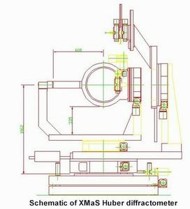
The 11-axis Huber diffractometer was installed in 1997. The vertical (z) translation exists to permit alignment of the sample to the three possible beam positions: white unfocused (z = 0 mm); monochromatic unfocused (z = -20 mm); monochromatic focused (z = 205 mm). Since the mirror deflects the monochromatic beam upward by 9 mrad, the facility to tilt (±1°) is provided in order to maintain perpendicularity between the focused beam and all horizontal circle axes. A horizontal translation (x) is present to centre the diffractometer in the beam. With the use of the SPEC software, orientation matrices may be defined in either vertical four-circle (phi, chi, omega, 2-theta) or horizontal four-circle (phi, chi, omega (horizontal), 2-theta (horizontal)) scattering geometries. In either of these geometries one may still drive/scan the two out-of scattering-plane circles. For surface diffraction or to control the angle of incidence and/or the exit angle between the x-ray beam and the sample surface, it is possible to use all six circles to define orientation matrices using specific versions of SPEC sixc or psic.
 |
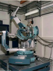 |
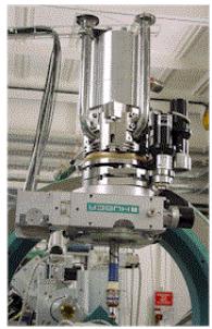
The physical layout of the diffractometer is shown above together with a picture of the device. Two multi-position plates at the front and rear of the base can be used to mount user equipment. All metallic parts around the sample circles are of non-magnetic material. The Huber 512 Eulerian cradle carries a 1003 sample goniometer head on the phi circle. There is a 10 mm diameter hole in the head and the distance from the base of the hole to the centre of rotation is 43.5 mm. Although not shown on the drawing, the detector arm is equipped with an X95 compatible mounting rail able to carry detectors and any of the modules, as described for the beam delivery system. This permits the minimisation of air in the beam path.
Polarisation Analyser
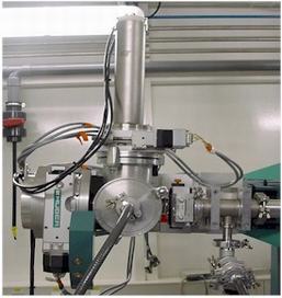
The three-axis XMaS polarisation analyser, shown below, has been designed to facilitate the study of changes in the polarisation of the x-ray beam after diffraction from the sample. The in-vacuum design allows the device to be used at low energies (~3 keV) which is particularly useful, for example, in experiments performed at uranium M-edges. The theta axis allows alignment of the analyser crystal to a diffracting condition, with theta Bragg at, or close to, 45°. The second rotation axis allows rotation of the diffracting plane of the analyser crystal about the scattered beam. Any component of the incident polarisation lying in the diffracting plane will go to zero on charge scattering for theta Bragg = 45°. The third linear axis allows translation of the detector in a 2-theta geometry in order to track the diffracted beam. Conventionally, for vertical scattering experiments, the incident polarisation is referred to as sigma polarised and any component orthogonal to it (i.e. vertically polarised) as pi polarised. Thus, by positioning the rotation about the beam such that the diffracting plane of the analyser crystal is vertical, one is sensitive only to the sigma polarised component and conversely a horizontal analyser crystal diffraction plane measures the pi component. The choice of analyser crystal depends on energy.
Full technical details of the polarisation analyser can be found here.
 |
Conventional Analyser
This is a conventional Huber analyser (415, two circle goniometer) which carries a Huber goniometer head (1001, with two translations and two arcs). Both Si (111) and Ge (111) crystals are available for use with this analyser.
Cryostat mounts
Both manual and motorised mounting systems for the APD cryostat fit into the Huber 410 phi circle. The manual Huber 5012 mount utilises dovetail linear slides for the X and Y translations, driven by manually adjusted screw threads. The Z translation consists of a sleeve and cylinder linear guide adjusted by a large threaded ring. These slides and the way they are adjusted makes precise and reproducible movements very difficult to obtain. Since these adjustments are usually not motorised, many hours of useful beamtime can be lost trying to find a "sweet spot" on a crystalline sample. Also, problems are encountered with this type of mount whilst tightening the screws to lock these translations in place. During cooling the cryostat contracts, sometimes by more than 0.5 mm and the sample alignment thus becomes very difficult. However, once the cryostat is fixed in place it is very stable.
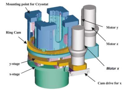
The motoried Huber 5012.12M mount has been designed to facilitate and thereby save time during sample align. It fixes to the diffractometer in exactly the same manner as the manual version and has the same translation limits. The three linear translations (X, Y and Z) are mounted onto high precision linear bearings. The independent X and Y movements are obtained by mounting a cam onto the shaft of a stepper motor with a 100:1 harmonic drive gearbox to minimise backlash. This cam is mounted within two linear bearings, thus allowing movement perpendicular to the axis of the motor (X and Y) with a minimum of backlash. The Z translation is guided by high precision linear bearings and driven by a stepper motor with a 100:1 harmonic drive gearbox via a large toothed ring cam. The cryostat and Z stage are mounted upon cam followers and as the large toothed cam turns, this provides the Z translation. This stage is held in place on the cam by eight strong springs.
Technical details can be found here.
 |
 |
| 3D model of the motorised XYZ mount | Motorised XYZ mount allowing precise alignment of a ARS (APD) cryostat |