
Manufacturing
Manufacturing was a very important factor in this project. It took many iterations and decision making to get to a finished product that we all liked. This page will aim to cover various aspects of the manufacturing process, including; material selection, manufacturing method, and the choice of various software that was used.
Material selection and manufacturing method were decided in parallel as the decision of one influences the decision of the other. Software called CES EdupackLink opens in a new window was used to narrow the material selection using certain criteria and a decision matrix was created to display the potential manufacturing options and weigh them against each other.
Material Selection
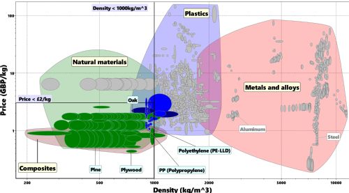 |
Stage 1: Price vs Density In order to satisfy our aims for mass manufacturing, the price was a major variable for Stage 1 of the selection phase. This was compared to density to ensure maximal material can be received from suppliers. |
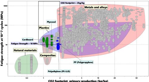 |
Stage 2: Fatigue Strength vs CO2 Footprint As in stage 1, boundaries were set for each criteria and are shown by the black box. Plywood falls within this box with the highest fatigue strength of the selection and a mid-range CO2 footprint. It satisfied our requirements whilst being realisable, unlike other materials such as cardboard that would not have produced a quality product. |
Manufacturing Method
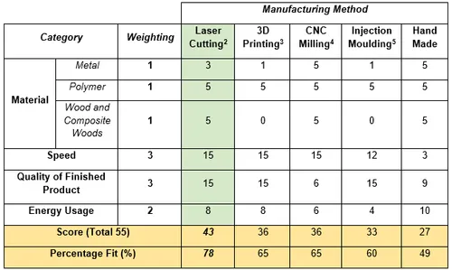
This decision matrix was created to evaluate the various manufacturing methods available to the project. Each category was given a weighting based on its importance and how confident the score assigned could be. The manufacturing method that produced the highest score was Laser Cutting with a score of 45 out of 55, a 78% fit. This aligned perfectly with the current best material from the material selection, plywood.
 |
Computer Aided Design (CAD) Choice
|
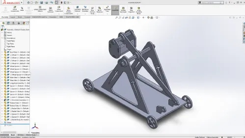
The CAD software that our group decided to use is called Solidworks. We chose to use this program due to our familiarity with it as well as having access to the student license from the University. It also ticked all of our technical boxes and allowed all the parts to be created separately and assembled at the end, as it is done when laser cutting. This meant there would be no surprises when it came to assembling the components. |
 |
LASERCAM and Deepnest
Two other software that we used were LASERCAM and Deepnest.
LASERCAM 2D was used for compiling the drawings ready to be sent to the laser cutter. We chose to use this software due to its availability within the Buildspace at the School of Engineering.
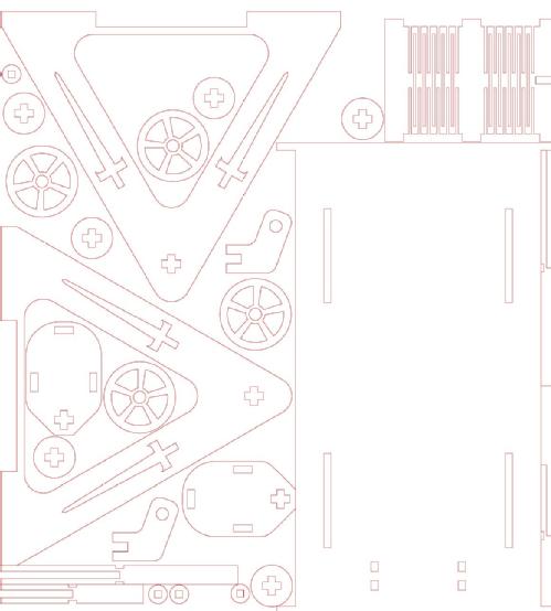
Deepnest was used to arrange the all the components in the optimal positions. This saved us having to manually arrange them, which was a massive time wasting activity and is difficult to get right when there are lots of parts, all different shapes and sized. Below you can see the optimised positioning for the parts, with a 1mm gap between them allowing us to draw tabs connecting components to the frame so they can be easily popped out.
 |