Build a Sensor
Designing Sensors
Objective: Build one sensor from the examples in this pack. Your sensor should respond to an input and create an output using the kit in the components box.
Why do products need sensors?
|
Almost everything you have ever bought will have been examined by or contain a sensor.
A sensor causes a change in an electrical system when a change in the real world happens. If you’re going to design a device that has a purpose or a function – there’s a really good chance that you’ll need a sensor in there somewhere to help your creation interact with the real world. |
 |
What should you do?
- Build a simple circuit following the Getting Started guide on the next page.
- Then, pick an example circuit from the later sections and recreate it.
 |
These are low-tech sensors for you to work through. The questions for sensor design are:
|
This activity aims to get you started with prototyping and designing a new device from scratch. It’s about using the equipment you have got and trying to see how far you can take it.
Getting Started
Let’s start by building a simple circuit. We’re going to wire from positive (the red wire on the battery pack) to negative (the black wire on the battery pack).
Safety:Never let the red and black wires from the battery pack touch each other.Connecting them directly creates a short circuit, which could cause a fire. |
 |

- Add two AA batteries to the battery case.
- Attach the 1st crocodile clip to the red wire coming out of the battery case and the resistor. The resistor protects the LED from damage.
- Attach the 2nd crocodile clip to the other end of the resistor and the long leg of the LED.
- Attach the 3rd crocodile clip to the shorter leg of the LED and the black wire coming out of the battery case.
- Switch on the battery case to light the LED!
Tape (provided in the box) will help keep the connections secure while building your circuit.
Example Sensors
Moisture Sensor
What’s the point?
Lots of people are suddenly trying their hand at gardening. The hard part is remembering when to water the plants to stop them dying! This device should help.
How can we build one?
Wet soil will conduct electricity but dry soil won’t.
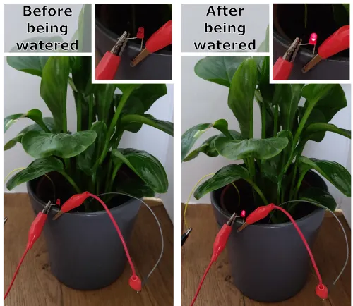
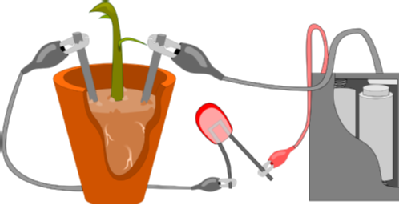
- Push two bits of metal into some soil – not too far apart, but make sure they don’t touch. The jumper leads would be ideal for this but you could also use a paperclip or a coin.
- Connect your circuit up to it – you’ll need your batteries and the crocodile clips. Add an output to your system by connecting up the LED.
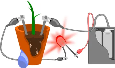
- Water the soil – wet soil will conduct electricity and your output will come on. As the soil dries the LED will get dimmer until it turns off.
 |
 |
|
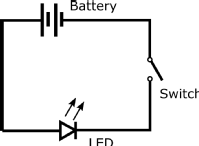
A circuit diagram of this sensor looks like this. In this case, instead of a switch we have the soil. Remember that dry soil does not conduct electricity but wet soil does? This means that when the soil is dry, the switch is open. When the soil is moist, it can conduct electricity, and so the switch is closed and current can flow. |
 |
How would you turn this into a useful device?
The light turns off in this set up when we need to be alerted most. This means the light will be on most of the time which will be especially annoying at night and will cost a lot in batteries! Instead, we want the light to come on when the soil goes dry to catch your attention and remind you to water the plant. To do that, we would need some more complicated components. We could write a program if we had a circuit board like a MicroBit.
Pressure Sensor
What’s the point?
You have seen, used or own plenty of devices that use buttons – this is a low-tech version.
How can we build one?
 |
 |
 |
 |
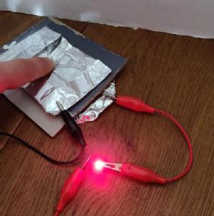 |
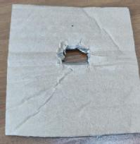
- Cut a hole in the middle of a piece of cardboard. You could use a part of the box the components came in. Be careful doing this. You could fold the cardboard in half and then use scissors to make a hole in the middle.
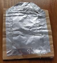
- Tape a big piece of foil onto one side of the cardboard. Clip one of your wires onto this piece of foil.
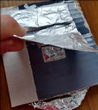
- On the other side of the cardboard attach another piece of foil but this time only tape it to the cardboard on one edge. Place your clip onto the edge of the foil opposite the tape you use to secure the foil in place.
- Add the resistor into this set up. Foil has very little resistance itself and we don’t want to damage the LED.
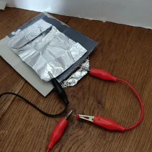
- Connect up the LED into the circuit.
- Push down on the foil over the hole in the cardboard and your LED will light up!
 |
 |
How would you turn this into a useful device?
| This probably won’t last long before it breaks and it’s huge – imagine TV remotes if buttons were this big. Buttons typically use a plastic case with a spring inside. When you push down on the top of the button you press together two metal connections and complete a circuit. When you let go the spring pops the metal contacts back apart and breaks the circuit. | 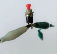 |
Tilt Sensor
What’s the point?
An example might be an elderly person living alone might fall over. We want to help! If they kept a device with them that could alert someone if the sensor detected ‘tilt’ we could help them stay safe.
How can we build one?
To detect tilt we need something that will move when it is tilted and a way to detect that movement. Since water always flows downwards – thanks gravity – and can conduct electricity, we can use water to complete a circuit when all is well but break the circuit if something goes wrong.
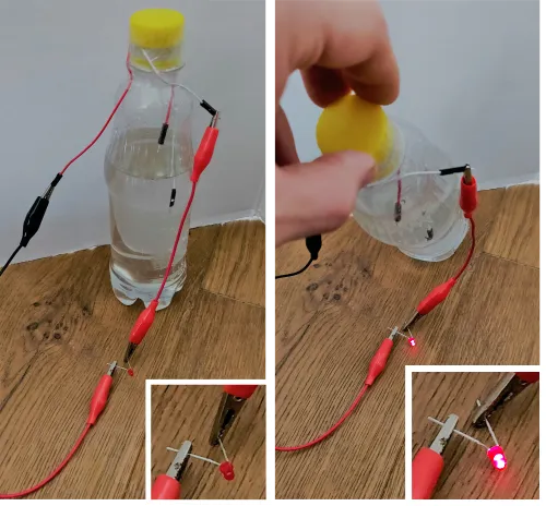
- Take a drinks bottle or another container with a lid (to avoid spills).
- Add water until the bottle is about 2/3 full. This works better if you can add salt to the water.
- Place the jumper lead wires inside the bottle and move them up and down until one is underneath the water and the other is about a centimetre above the water.
- Loosely place the cap back on the bottle. You won’t be able to screw it on tightly or you’ll cut the wires and the circuit will break. I used sticky tape around the lid to hold the wires in place and make sure the bottle didn’t leak.
- Connect up your circuit. You’ll need your batteries connected up to an output like the LED and then attached to the jumper leads.
- Tilt the bottle and the LED will light up!
Another way to set this up would be to have both leads, or unfolded paperclips, in the water to start with. This way, while the tilt sensor is upright, a complete circuit exists. Tilting now breaks the connection and the light goes out.
How would you turn this into a useful device?
A radio transmitter could send a signal to say that all is well – until the circuit is broken when the device is tilted and the radio signal stops. Someone else can have a device that makes a loud noise when the radio signal is lost and they will know to go and check in on the person with the sensor.
Position Sensor
What’s the point?
If we didn’t have position sensors, touch screens wouldn’t be possible. A touch screen can detect the position of your finger on the screen.
How can we build one?
The screen can detect the position of your finger anywhere across it, not just how high up or how far to the left or right it is. We can build a much simpler system here that can detect how far apart two metal contacts are. This is a far cry from a touch screen but it’s a start.
 |
 |
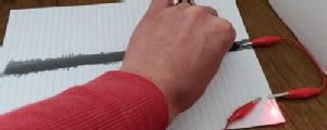 |
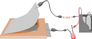
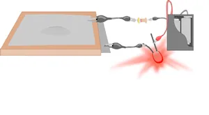
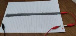
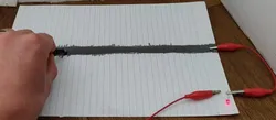
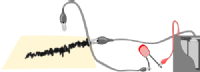
- Take a pencil with a lot of graphite in it (the 4B pencil in this box should do nicely) and shade a strip along a piece of paper. Make sure it is a really dark box with no gaps.
- Clip one of your wires onto the edge of the paper and make sure the pencil shading goes right under the clip.
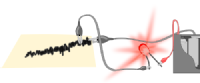
- Make a connection with the other clip at some point on the pencil line and try sliding it closer to and further from the first clip. Watch what happens to the brightness of the LED.
| This is an analogue sensor – it has lots of different positions. The pencil-shaded strip is a variable resistor. Graphite in pencils can conduct electricity but the shaded section is so thin that there is a lot of resistance. The longer the distance between the two metal clips across this pencil-shaded strip, the higher the resistance in the circuit and the LED gets dimmer. | 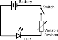 |
 |
 |
 |
How would you turn this into a useful device?
A touch screen device is made up of a grid of these set ups. When you touch a position on the screen you complete a circuit in the row and column where your finger is. Clever programming in the computer that controls the screen can work out the exact position of your finger by which rows and which columns currently have electricity flowing through them.
Now what?
If you’ve built one of the sensor designs here, you’re well on the way to designing a real product.
You might have an idea for what you want to build and you might know about other components that aren’t in this box! Feel free to sketch out ideas and make plans for a device that you could build. These designs are here to show you that low-tech options exist for making sensors and devices.
Now you know how sensors work by responding to an input and creating an output. You can start to put those ideas into practice when you carry on with this competition and think about whether your design needs a sensor. If it does, what input is it waiting for? What output will it give?
Troubleshooting
Positive and negative
Your batteries have a positive and a negative end. On normal AA batteries the end with the lumpy bit sticking out is the positive terminal. Typically we attach a red wire to the positive terminal and a black wire to the negative one. If the wires you have aren’t red and black, don’t worry! So long as you know what’s going on that’s all that matters.
Avoiding short circuits
We do need to be very careful not to short-circuit the batteries. You’ve probably heard that term a lot – but what does it actually mean? If you connect up the positive terminal of a battery to the negative terminal without doing anything else in the circuit the electrical energy will just flow straight through without being converted to a different type of energy. If there’s a motor you turn electrical energy into kinetic energy. If there’s a buzzer it’s sound energy. If there’s an LED then you get light. Without any of these components the electrical energy flowing around the circuit will end up being converted into heat. A lot of heat. The components might get really hot and in some cases this could damage the battery, burn you, or worse. Please be very careful and make sure that you turn the switch on the battery cases off when not in use to make sure that an accidental short circuit does not happen.
Common problems
If you expect your circuit to work but for some reason it doesn’t there are a few easy steps to try out.
- Check what you are expecting to happen when the circuit is complete – is the light supposed to come on?
- Check that the crocodile clips are firmly making contact with the wires and your device the whole way around your circuit.
- If you’re using the LED make sure the positive end of the circuit is clipped to the longer leg of the LED.
- If you’re using foil check if it has ripped and broken the connection.
- Remove components one at a time and check if it fixes the circuit, rather than making drastic changes all at once. This will help you find which connection was the problem.
Useful Words
There are a few words we are going to need to use for describing these circuits.
|
Digital |
Only has an on and an off position. An example would be a normal light switch – the lights are either on or off. |
|
Analogue |
Has lots of positions in between fully on and totally off. An example would be a volume dial that you can turn to make the volume a tiny bit louder or quieter as the dial goes around. |
|
Input |
For most products this will be what you do the product. You might press a button or flick a switch. Some sensors might be measuring something like the temperature as their input. |
|
Output |
What the system does when the input changes |
|
Conductor |
Parts of your creation that will let electricity flow through. |
|
Insulator |
Parts of your creation that will block electricity and break a circuit. |
|
Current |
The flow of electricity through the circuit. Think of a race – the current is how many runners are running past you every second. |
|
Voltage |
How hard the current is being pushed around the circuit. If we’re still thinking about a race – increasing the voltage is like putting a big dog behind the runners to scare them and force them to run. |
|
Resistance |
How hard it is for electricity to flow through a part of your circuit. Resistance is measured in Ohms and the symbol is Ω |
|
Resistor |
|
|
Variable resistor |
|
|
LED |
Useful tip: Connect the positive end of your battery pack (the red wire) to the longer leg of the LED. |
 A circuit component that does conduct electricity but not very well. These are used to decrease the current that is flowing around a circuit at any voltage. You might use a resistor to decrease the brightness of a bulb, for example. Some components may be damaged if too much current flows through so a resistor is useful to protect them.
 Is it unhelpful to say that this is a resistor that you can vary? Using a normal resistor to protect your circuit is great if you have a resistor with the exact resistance value you need but what if you want to change the brightness of a bulb in the circuit? What about if you want to control the resistance of your circuit? That’s where you need a variable resistor.
 A Light Emitting Diode. Current can only flow through in one direction. The device lights up as the current flows through. The brightness of the LED will increase as more current flows through. The colour of the LED depends on what it is made of.