
Ion Scattering
Ion scattering techniques operate across a large energy range, of 1keV to > 10MeV, each with different benefits and different aspects that can be investigated with each technique.
Basics of Ion Scattering
Compared to other surface analytical techniques, the physics governing ion scattering is relatively simple. Being a real space technique, the complexity of converting reciprocal space data to real space is not required, and the overall equation governing collisions can be simply shown as a binary collision model.
Where ,
is the mass of the incident ion,
is the mass of the target atom,
is the kinetic energy of incident ion,
kinetic energy of scattered ion, and
is the scattering angle with respect to incident trajectory [1].
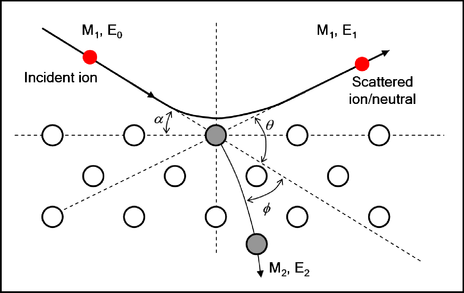
Schematic diagram of ion-surface atom binary collision model.
With a monoenergetic ion beam, and knowledge of ,
and
, measurement of
leads to a determination of the target mass
. Selecting an appropriate scattering angle, in particular 180o leads to a simplification of the equation to:
To obtain quantitative information about the species present at the surface of a material it is necessary to understand the interaction potentials, due to the effects of ion neutralisation and scattering cross-section.
Interaction Potentials
Ion scattering is described by a Coulombic interaction of the two particles, but can only be considered to be purely Coulombic at high energies (MeV scale). At low energies, the longer interaction times mean that electron screening must be taken into account. The interaction potential falls off faster than , with the Coulombic interaction being multiplied by a screening function commonly used to represent this.
Where a is the screening length, and is the screening function. This potential can be described in two different ways; a Moli´ere approximation to the Thomas-Fermi model [2], or the Ziegler-Biersack-Littmark (ZBL) [3] function, although the ZBL potential has been shown to be inappropriate for CAICISS analysis [4]. Using this the scattering angle
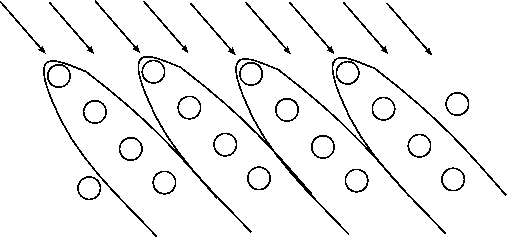
and impact parameter b can be computed, giving a set of trajectories. The Coulombic interaction creates shadow cones behind the target atoms, and any other atom which is in that cone will be sheltered from the flux and thus not contribute to the signal, as shown below.
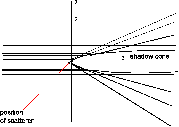
Scattering trajectory of an incident ion displaying shadow cones on atoms in following layers.
It can also be seen that at the edge of the shadow cone trajectory focussing occurs, thus increasing detected intensity. At low incident energies these shadow cones can be a large fraction of the interatomic spacing in the surface region.
Low Energy Ion Scattering (LEIS)
The use of low energy ions has two advantages for surface studies, high cross-sections for ion-atom interactions and higher neutralisation probabilities for noble gas ions due to reduced velocity. This leads to a sensitivity to only the near surface region (~ 3 - 5 atomic layers) [5].
Early experiments, such as those performed by Smith [6] suggested LEIS was a good technique for the determination of surface elemental composition. Any ions undergoing multiple scattering events lose energy, whilst deeply penetrating ions are extremely likely to be neutralised [1]. The early detection systems were electrostatic analysers, which would detect scattered ions, thus making LEIS experiments truly surface specific.
In the field of LEIS there are several variations to the technique that have been introduced to address the neutralisation problem, allowing the near surface structure and composition to be studied. These can all be classed as impact collision ion scattering spectroscopy (ICISS). The use of alkali metal ions (ALCISS [1]}, which have a reduced ionisation probability), detection of neutrals and ions (NICISS [1]), both of which are operated in a time-of-flight (TOF) mode. The TOF mode is useful as any scattered ions will have a reduced velocity due to the energy exchanged in the collision, thus meaning it will have a longer flight time to the detector, but no ions that haven't been scattered make it to the detector.
Co-axial Impact Collision Ion Scattering Spectroscopy (CAICISS)
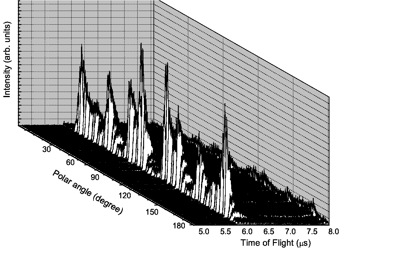
CAICISS is a technique which utilises the 180o backscattering geometry. By looking at a specific incidence angle it is possible to build up an intensity profile that can identify the different elemental species in the surface region. If the sample is rotated on the polar axis then a 3D plot (counts vs TOF vs angle) is produced. This is then filtered for each element to give the 2D plot.
 |
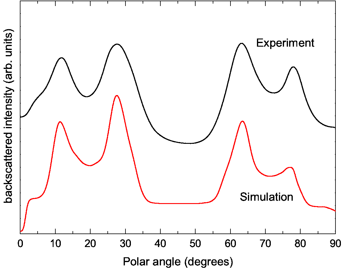 |
Example 3D plot produced by a polar scan, showing counts vs TOF vs polar angle, and example spectra of a Cu(100) sample for the polar region of 0 - 90o, including the comparison to simulation.
The spectrum shows several important features, particularly for determining the structural and chemical makeup of the crystal. Starting at 0o, i.e. parallel to the surface, every atom is in the shadow cone of the previous atom. Increasing the angle of incidence leads to the surface atoms emerging from the shadow cones, until the edge of the cone from one atom is directly focussed on the next atom in the chain, thus producing a large increase in the backscattered ion yield, known as the surface peak and this effect arrives due to trajectory focussing [1]. The relevant angle at which this surface peak arises is known as the critical angle, which is related to the interatomic spacing of the atoms at the surface. This is vitally important for characterisation of the surface.
Further increasing the angle of incidence leads to atoms in the second layer emerging from the shadow cones. When the shadow cone is directly focussed on a second layer atom again we see an increase in backscattering yield. This is used to determine interlayer spacing, and can be used to look for surface relaxations, where the topmost interlayer spacing may change from that of the bulk due to effects such as adsorption of other elements onto the surface, or temperature. A similar effect is seen when focussed onto the third layer atoms. Depending on the crystal structure it may be possible to observe contributions from deeper layers.
Medium Energy Ion Scattering (MEIS)
In contrast to low energy ion scattering, medium energy ion scattering tends to use H+ or He+ incident ions. With an incident energy of 50 - 400 keV, with usual operation at most facilities of typically 100-200 keV incident beams. Due to the increase in energy, there is increased beam damage at the surface of materials, making MEIS a technique that is inappropriate for materials susceptible to high beam damage. The shadow cones of a MEIS beam are much narrower than that of a LEIS beam, leading to a requirement of specific alignment geometries to understand surface structure. This will be detailed further in the surface structure determination section below.
Channelling and blocking
Due to the effect of the Coulombic field, the ions will be deflected such that a region of no flux is created behind the target atoms, this is the shadow cone as mentioned previously. MEIS requires the incident beam to be aligned to a major crystallographic direction to illuminate only the atoms in the outermost layers, and thus ensure surface specificity. Most of the incident ions will suffer small deflections on their passage through the solid, channelling them between the rows of atoms, but this is only relevant for small penetration depths, as at large penetration depths, successive deflections result in an increased transverse momentum, thus destroying the channelling effect, and causing the effect of dechannelling. For ions on their way out of the surface from backscattering
Surface structure determination
To determine the surface structure of a material using MEIS, the crystal must be aligned along a major crystallographic direction, for both incident beam, and outgoing backscattered ions. This is known as the double alignment geometry. To accurately determine a structure more than one combination of these must be used to reduce the number of models that could produce the blocking dip pattern that would otherwise be observed from the data.
Depth profiling
Using MEIS as a low energy form of RBS it is possible to perform depth profile analysis. Buried layers of a material within a sample can be observed, and their separation can be observed as a set of peaks at different energies. Using the kinematic factor for the appropriate target, this can then be converted into depth within the sample at which that elemental layer is present. The analysis is not quite that simple though, due to the effects of energy straggling from the inelastic collisions of ions with the electron clouds of the atom. This straggling leads to the Gaussian broadening of the signal, so layers can appear to be deeper than they are before this effect is corrected for.
Rutherford Backscattering (RBS)
Rutherford backscattering is a high energy ion scattering technique. Incident energies are of the order many MeV. It is not a surface sensitive technique, and is used mainly for compositional analysis at different depths within a sample. The different compositions at different depths can be obtained by investigating the shape of the peaks in a scattering spectra, along with the energy at which the backscattered particles have arrived at the detector. The shift in the peaks observed will be due to inelastic losses when the ions scatter off the nucleus, or electrons within a sample. Like with MEIS, it is important to use blocking and channelling directions within the sample to reduce the level of background signal
Return to structural characterisation
References
- H. Niehus, W. Heiland, and E. Taglauer, Surf. Sci. Rep. 17, 213 (1993).
- G. Moli`ere, Z. Naturforsch 2a, 133 (1947).
- J. Ziegler, J. Biersack, and U. Littmark, The stopping and ranges of ions in solids Vol. 1, Pergamon(New York), 1985.
- M. Draxler, M. Walker, and C. McConville, Nucl. Inst. & Methods B 249, 886 (2006), Ion Beam Analysis - Proceedings of the Seventeenth International Conference on Ion Beam Analysis.
- D. P. Woodruff and T. A. Delchar, Modern Techniques Of Surface Science - Second Edition, Cambridge University Press, 1994.
- D. P. Smith, Surf. Sci. 25, 171 (1971).