
Carrier Type
As mentioned on the previous page, for a simple metal and doped semiconductors in which there is only one type of charge carrier (either electrons or holes) the Hall voltage VH is given by
where I is the current across the plate length, B is the magnetic flux density, d is the depth of the plate, e is the electron charge, and n is the charge carrier density.
The Hall coefficient is defined as
where j is the current density of the carriers. In SI unites this becomes
.
In general, the Hall voltage is not a linear function of magnetic field though it can be easily calculated by assuming that all carriers have the same drift velocity.
This can be achieved via one of two assumptions:
- All carriers present are of only one type.
- carriers of both types are present.
One Type of Carrier
This is the same as the general case mentioned above, with the Hall coefficient thus given by
.
When one carrier dominates, the conductivity of the material is σ=eqμ with μ being the mobility of the charge carriers. Therefore,
.
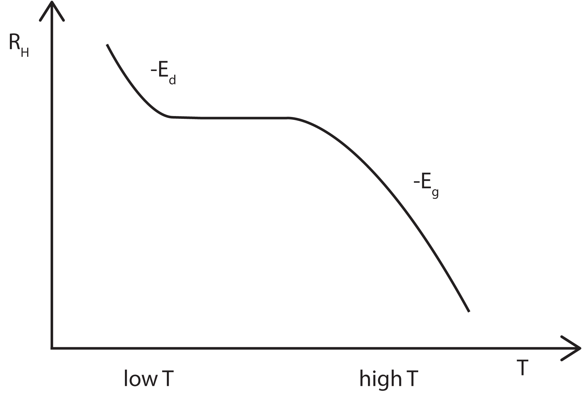
This simple expression for R allows both the band gap energy and the donor level energy to be determined by studying the change in R with temperature.
RH(T) depends only on n(T), the charge carrier density. At low temperatures, there is only enough thermal energy to excite carriers from the donor levels (Ed) close to the conduction band edge up into the conduction band. Therefore it is expected that RH will decrease linearly with a slope proportional to -Ed, before plateauing out once all the donors have been ionised. At higher temperatures, carriers can now be excited across the band gap and thus the Hall coefficient will again begin to decrease, this time with a slope proportional to Eg.
Two Types of Carrier
This approach is useful for intrinsic and lightly dopes semiconductors. The mobilities of both of the carrier types enter into the calculation and weighted average must then be used. Here,
.
where μh and μe are the hole and electron mobilities and p, n are the respective carrier densities.
This equation is derived starting with the equations of motion for electrons and holes in a semiconductor crystal [1]
which have the steady state solutions:
so that the current density, j, is
.
Here it is common to assume the conventional geometry, in which the current flows along x, the magnetic field is applied along z and the Hall field appears along y. The boundary conditions in this geometry require , but this does not mean that the hole and electron currents in this direction are individually zero, merely that they are equal and opposite.
Noting that the y components of the carrier velocities are linear in B and keep only terms up to the first order in B, then the previous equation becomes
where we have used the steady state solutions to obtain the last line.
Cancelling between these two equations gives
.
This from the definition of the Hall coefficient (in this geometry)
)
and therefore
as before.
This is more complex then the previous expression for RH. The band gap energy may still be obtained but a different method has to be employed. This method is described in more detail in the Temperature Dependence sub-page.
In general μh < μe so if p>n then R may become negative. This is known as inversion and is obviously a characteristic of only p-type semiconductors.
References
- Kittel, Intoduction to Solid State Physics, Wiley, 2004
- Ashcroft and Mermin, Solid State Phsycics, Brooks Cole, 1976
- Hook and Hall, Solid State Physics, John Wiley & Sons, 1991