Tiles for Tales
Tiles for Tales
Contents
Introduction | Create a Tile | Program a Tile | Hardware and Software | Tiles for Tales @ Mozfest | Connect to your home network | Use ScratchX | Worksheets
Introduction
The Tiles for Tales project explores links between the craft of story telling and technology. It shows how physical computing activities can be incorporated into collaborative activities, for example, used to support story telling activities by children.
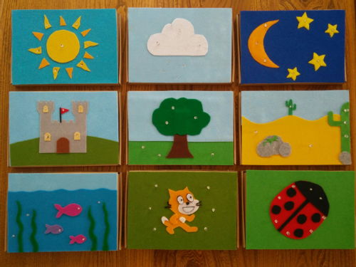
A set of tiles are created, each tile represents a character or scene, and the tiles can then be used in similar way to story stones (or story dice) to narrate a tale, with each tile being programmed directly using microBlocks (www.microblocks.fun). (Earlier versions used the Tilenet software developed by James Johnston which gave the ability to control multiple tiles from the same Scratch script.)
This project gives a creative context to simple control activities like blinking LED's. Individuals or small groups can develop a tile, and working together a class can create a set of tiles.
These examples use pre wired led's with resistors and terminal connector blocks to make it easy to build circuits from the start, but circuits could be created in a wide range of ways.
This project has been presented as a poster at Scratch MIT 2016 Conference on August 3rd - 6th, Cambridge, USA; and as workshop at Scratch 2017 Conference, July 18th - 21st, Bordeaux, France; Scratch 2018 Conference, July 26th - 28th, Cambridge, USA; Scratch 2019 Conference, 23rd - 25th July, Cambridge, UK;
- Creating a tile
- Program a tile
- Hardware and Software
- Tiles for Tales Poster, Scratch MIT 2016
For more information please contact: m dot j dot low at warwick dot ac dot uk

Create a Tile
To gain an insight into the how the technology behind the tiles work, please read the section on Hardware and Software and then how to use the ScratchX extension to control the tile. Its really useful to have an example tile to play with, so before starting a large project, first build a tile to have an understanding of the possibilities and first hand experience of what is involved.
Note:- the wiring on tiles to the microcontroller can be done in a variety of different ways. Our examples below use pre-wired LEDs with resistors already included, and terminal connector blocks.
Tile Base
Find a suitable box to act as the base of a tile. My examples use folding cardboard mailing boxes, suitable for a book. They are cheap to purchase and have sufficient depth to store the electronics, alternatives would be cardboard shoeboxes, or other box containers. Think about what is best for the application you are creating.
Design Tile
 Design a simple scene, and then plan how to illustrate it with coloured LEDs. Keep it simple, don’t use too many LEDs; less than 6 to begin with. Every LED introduces 2 wires that need to be connected, and the wiring can quickly get complicated. Think about how to group LEDs together. All LEDs connected to the same pin will have the same behaviour. LEDs that operate together (connected to a single pin) should all be wired in parallel. This means they will all be equally bright when switched on.
Decorate Tile
Decorate the tile lid based on your earlier design. Felt works well, as does coloured paper and pens to create the design. If you use any wet materials, its essential that you allow sufficient time for them to completely dry, also avoid using conductive materials like tin foil. Should any bare wires accidentally touch there is the possibility of creating short circuits and creating a fire hazard.
Build and test LED circuit
 Draw a diagram of the wiring in your circuits. The LEDs in my examples are already pre-wired with a resistor to protect the LED, and with a red (positive) and black (ground) connecting wires. A cheaper alternative would be to purchase LEDs and resistors - but the resulting circuit needs to be suitably insulated to avoid short circuits and being a fire hazard.
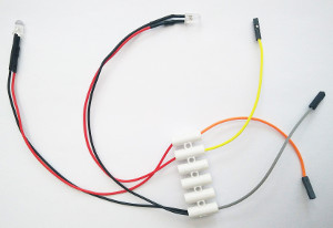
For short workshops we create a simple pre-wired harness, with 2 LEDs connected and pins ready to connect to the NodeMCU. The photograph shows 2 LEDs, each with its own circuit, connected using Terminal Connector Blocks. The red wire from each LED will be connected to a pin on the NodeMCU, the black (ground) wires can all be connected together to provide a single connection to ground on the NodeMCU.
Wiring up the Microbit
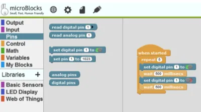
Connect the ground wire (black) to GND pin on the Microbit. Connect other wires to 0, 1 or 2 pins on the Microbit. In microBlocks you can control the pins using the 'pins' menu. LEDs can be switched on or off using the 'set digital pin' block or set to a specific brightness using the block 'set pin' block and using a value beween 1 and 1023.
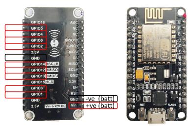
Wiring up the NodeMCU
Connect LEDs to suitable digital pins on the NodeMCU (shown in red) and connect the ground wires to one of the ground pins on the board. Note: not all digital pins are available for use. Please consult the microBlocks website for information if you wish to use the NodeMCU. http://microblocks.fun/nodeMCUSetupLink opens in a new windowLink opens in a new window
Next step
When your processor is wired up - then see the see the section Program a tile about how to control LEDs using your board.
Program your Tile
To program your tile, microBlocks is used (www.microBlocks.fun).
Make sure you have wired up your processor and LEDs as outlined on the Create a TileLink opens in a new windowLink opens in a new window page. In the example below the microbit is used as an example.
1. Start microBlocks on your computer and connect the microbit via the USB cable.
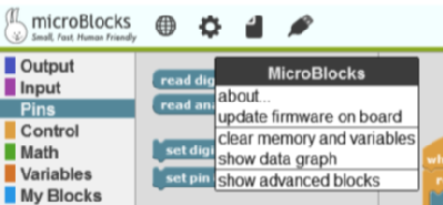
2. The first time you use microBlocks with a microbit, you need to download firmware onto the microbit. Click on the gears icon (settings), to get the menu as shown below. (Instructions for other boards is available on the microBlocks website - other boardsLink opens in a new windowLink opens in a new window.)
3. Next click on the USB icon to connect microBlocks to your board (2 along from the gears icon).
4. Write a script to control the LEDs connected to the microbit. This an example.
Example Scripts to TryLink opens in a new window
Hardware and Software
Each tile has a microprocesser inside that controls the LEDs.
Hardware: a processor (NodeMCU - based on ESP8266, or Microbit), one micro-processor per tile.
Software required: microBlocks - installed on your computer.
Other useful items for creating tiles.
- Multiple LEDs, I use LEDs that are prewired with a resistor for LED protection.
- Battery box compatible with microprocessor : 3 x AA batteries for NodeMCU or 3xAAA for Microbit
- Terminal Connector Blocks are useful for making simple circuits
- Crocodile clips for connecting circuits.
- box or other container to create your tile
- Felt or other material to decorate it.
Tiles for Tales at Mozfest
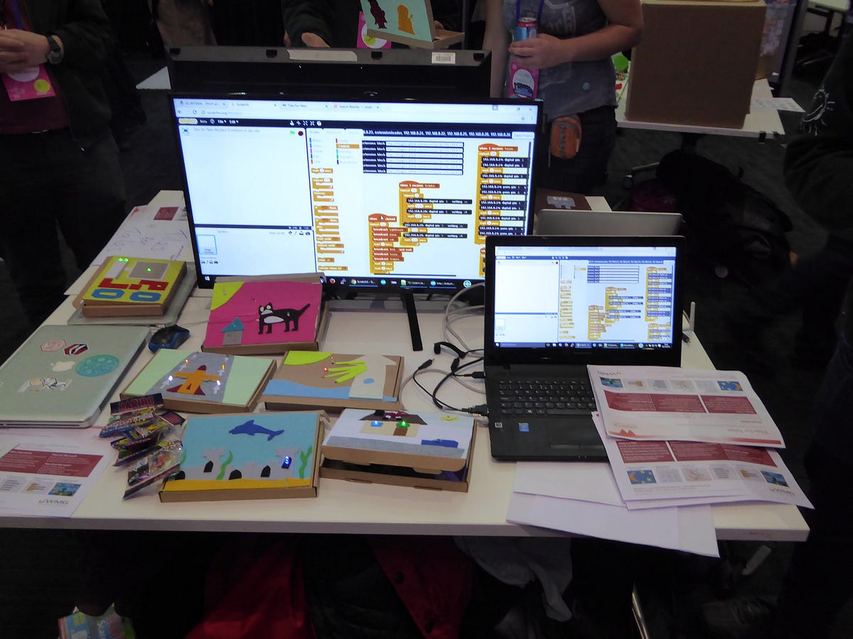
At the Mozilla Festival 2016, on the Saturday afternoon, the Tiles for Tales workshopLink opens in a new windowLink opens in a new window ran as part of the Youth Zone Activities at the festival. The Technology VolunteersLink opens in a new windowLink opens in a new window and collaborators spent a very busy Saturday afternoon with people of all ages, helping them to create their own interactive tile.
Workshop participants designed a tile using felt and cardboard to represent a character or scene, adding LEDs, wiring and a processor (based on the ESP8266) giving wifi control of the tile. The LEDs on the tiles are then controlled using ScratchX, a variant of Scratch.
The range of work produced by workshop participants was fantastic, we were stunned by the creativity of the tiles created, and were delighted to exhibit them on Sunday at the Mozfest Demo Fair. We met up with friends from the Coventry Coderdojo, and also Warwick Alumni attending the festival.
The Festival was a great experience for usLink opens in a new windowLink opens in a new window, and we really enjoyed being part of the Youth Zone activities. The Youth Zone at Mozfest was co-ordinated by Dorrine Flies and Andrew Mulholland, who ensured there was a wide variety of creative activities over the festival weekend for young people.

Connecting to your home network
Equipment required to complete a tile:
NodeMCU processor
Battery pack (3 x AA batteries)
Download tiles software onto NodeMCU:
www.warwick.ac.uk/tilesfortales/hardwareandsoftwareLink opens in a new window
Configuring Tile on home network
The NodeMCU acts as a wireless access point if it can’t find the tiles network when the NodeMCU is powered up. Usually its ssid starts with ESP followed by numbers.
1. Connect to the NodeMCU network.
Using your computer connect to the nodeMCU wireless access point. The password is:
tiles-for-tales
2. Load Config file
Startup your browser and navigate to:
http://192.168.10.1/config.html
This loads up a page to enter your node name (for ScratchX), the home ssid and password
3. Enter node name and h ome wifi parameters
On the config page enter your node name, home ssid and password. This will mean the NodeMCU will join your home network and will broadcast its own IP address every 30 seconds.
4. Find NodeMCU IP address
There are two ways of finding the NodeMCU IP address, one is to use a UDP app on a mobile phone to monitor broadcasts. The second way is to look at the wifi router and look for an ESP device.
5. Control tile using ScratchX
Once you’ve established the NodeMCU’s IP address on your home network, you can control it via the ScratchX website, first load estension_loader, and use it to load your tile commands.
ScratchX
An extension is created in ScratchX for each tile. Follow the instructions below to load an extension to control a tile:
- Using chrome browser, go to the ScratchX extension page: www.scratchx.orgLink opens in a new window
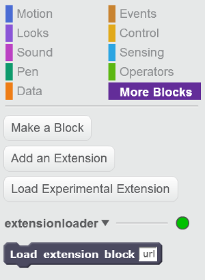
- There is a problem passing arguments into ScratchX. We've created a simple extension 'loader' which 'gets round' the problem of passing arguments. This extension loader can be loaded by clicking on 'Open extension URL' and pasting the URL: https://megjlow.github.io/extensionloader.jsLink opens in a new windowLink opens in a new window
- This creates a ScratchX block to load further extensions, with arguments:
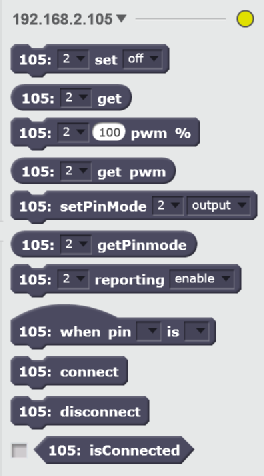
- Pull the 'Load extension block' into the scripts area and enter: https://megjlow.github.io/socket.js?ip=192.168.2.105 (replacing the IP address with the IP address of your NodeMCU). This loads the extension with commands to control the pins on your board:

- Click on the 'Load extension' block to run it, this will load in the extension with commands that enable you to control the NodeMCU pins:
- Multiple NodeMCU extensions can be loaded via this method.
- Many of the NodeMCU digital pins can be controlled via this extension. They can be set as input, output or pwm.
To help build your first tile see the section Create a Tile
Worksheets
These worksheets go through key steps to create an interactive tile and were created to support the Tiles for Tales workshop at Mozfest 2016: